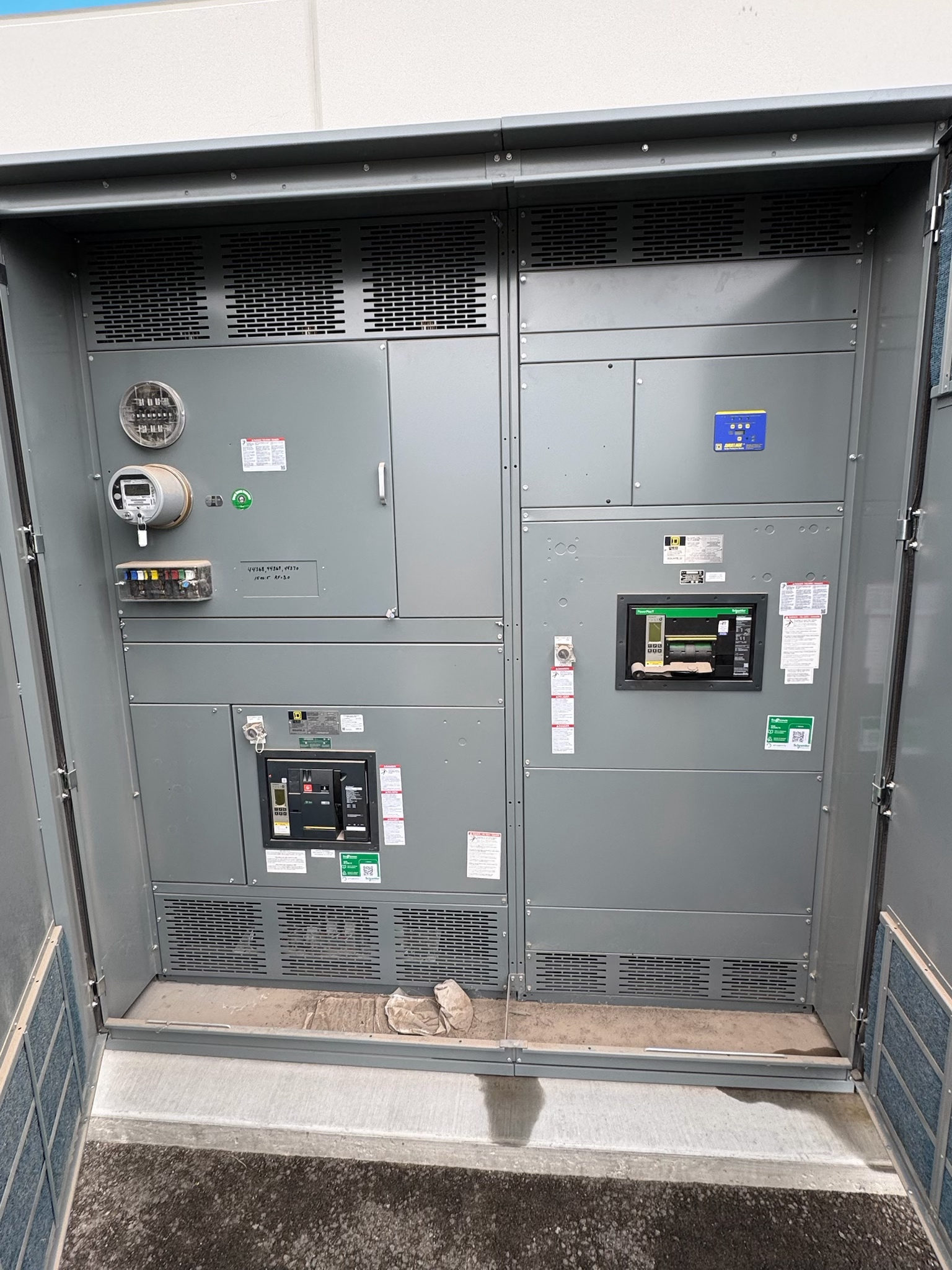
What Overcurrent Protection Means
Overcurrent protection is the coordinated use of devices and equipment features intended to respond when current exceeds an acceptable level for a circuit or component. The response may limit current, interrupt it, or signal another protective action, depending on the device and system design. Overcurrent can result from an overload, a short circuit, or a ground fault where the applicable protection scheme detects that condition. The term does not identify one universal device or setting: fuses, circuit breakers, relays, and associated sensors can perform different roles.
For a new switchgear project, protection must be considered as part of the electrical system, not as an isolated product feature. Equipment selection and settings depend on the application, available fault current, connected loads, conductor limits, and upstream and downstream devices. Qualified electrical professionals should establish requirements and verify the design.
Why Protection Design Starts With the System
The protective response needs to match the circuit it serves. A setting that is too low may interrupt normal load or expected starting current; one that is too high, too slow, or otherwise unsuitable may fail to protect conductors and equipment as intended. The design also considers what should remain energized when a fault occurs. Selective coordination may help limit interruption to the affected portion of a system, but its feasibility depends on device characteristics and the project’s operating requirements.
Useful inputs include the one-line diagram, system voltage, load characteristics, conductor data, grounding method, available fault-current information, and upstream and downstream protective-device details. Operating modes, such as alternate sources or ties, may change fault conditions. These inputs should be reviewed together before specifying new switchgear or protection components.
Inputs That Shape Device and Setting Choices
Selection is not based on nominal load current alone. The engineer needs to evaluate expected continuous and intermittent loads, motor or transformer inrush where applicable, conductor ampacity, equipment withstand and interrupting capabilities, and calculated fault-current conditions. The chosen device must be suitable for its circuit and installation, with ratings verified for the actual system. Enclosure, environment, available space, access, and the intended control or monitoring interfaces can also affect assembly design.
Protection options may include adjustable or fixed trip functions, fuses, electronic trip units, current transformers, relays, or communications interfaces, depending on the equipment and application. Do not assume every option is available or appropriate in a particular assembly. Identify required functions, measurement points, alarm signals, and control boundaries in the project documents, then confirm compatibility during design review.
Coordination, Interfaces, and Verification
Coordination studies compare device response characteristics across relevant operating conditions. Their purpose may include reducing unnecessary outages, protecting conductors and equipment, and supporting an intended sequence of operation. Results depend on accurate system data and the specific devices selected; a coordination claim should not be inferred from a product description alone. Where the project requires it, provide study assumptions and required deliverables to the responsible electrical professional.
Protection interfaces also need definition: control power, trip and close circuits, status contacts, metering signals, communications protocols, and connections to other equipment can affect scope. Acceptance checks and testing should follow the project specification and applicable requirements, with procedures established by qualified personnel. Confirm what documentation, settings records, and test evidence are expected before assembly release, and resolve discrepancies before energization.
Applying the Definition to New Switchgear
When specifying new switchgear, state the protective function and system conditions rather than relying on a general request for overcurrent protection. Provide the latest available one-line diagram, load schedule, fault-current or study information, device coordination requirements, and interface list. Identify source configurations, future provisions, and any operating constraints that influence protection. If information is preliminary, mark assumptions clearly so they can be checked rather than treated as final design criteria.
The equipment supplier can use the approved requirements to develop an assembly configuration and identify information needed to complete the design. Confirm which protective devices and interfaces are included, which settings are determined by the engineer, and which studies or tests are within the project scope. Applicable standards and any listing, including whether UL 891 applies to a suitable switchboard assembly, depend on equipment design and project requirements; do not assume coverage for every switchgear type.
A Practical Review Before Procurement
Before releasing a new switchgear order, compare the proposed equipment documents against the project’s one-line diagram and protection requirements. Check device types and functions, system voltage, fault-duty assumptions, load and conductor information, interface points, enclosure requirements, and coordination-study responsibilities. Resolve mismatches in source configurations, available fault current, or control wiring before approving the submittal. A clear division of responsibilities helps prevent gaps between equipment design, engineering studies, field connections, and commissioning.
For custom assemblies, provide the manufacturer with the project specification and a consolidated list of required options, documents, and review milestones. The US manufacturer described here builds in the USA with all-American components and can ship nationwide; lead time is determined by the project. These facts do not replace technical review. Have qualified electrical professionals verify ratings, settings, applicable standards, and acceptance requirements with relevant authorities before procurement and installation.
Project specification checklist
Use this checklist to organize the details for a project-specific review. Final ratings, applicable standards and equipment selections depend on the approved design.
| Item | What to confirm |
|---|---|
| System and fault data | Confirm system voltage, source configurations, grounding method, and available fault-current information for each relevant operating mode. |
| Load and conductors | Provide load characteristics, starting or inrush information where applicable, and conductor data for protection review. |
| Protective devices | Define required device functions and verify suitability, interrupting capability, and settings against project conditions. |
| Coordination scope | Identify coordination objectives, study assumptions, responsible parties, and expected study deliverables. |
| Interfaces and testing | Specify control power, signals, communications, acceptance checks, test records, and documentation responsibilities. |