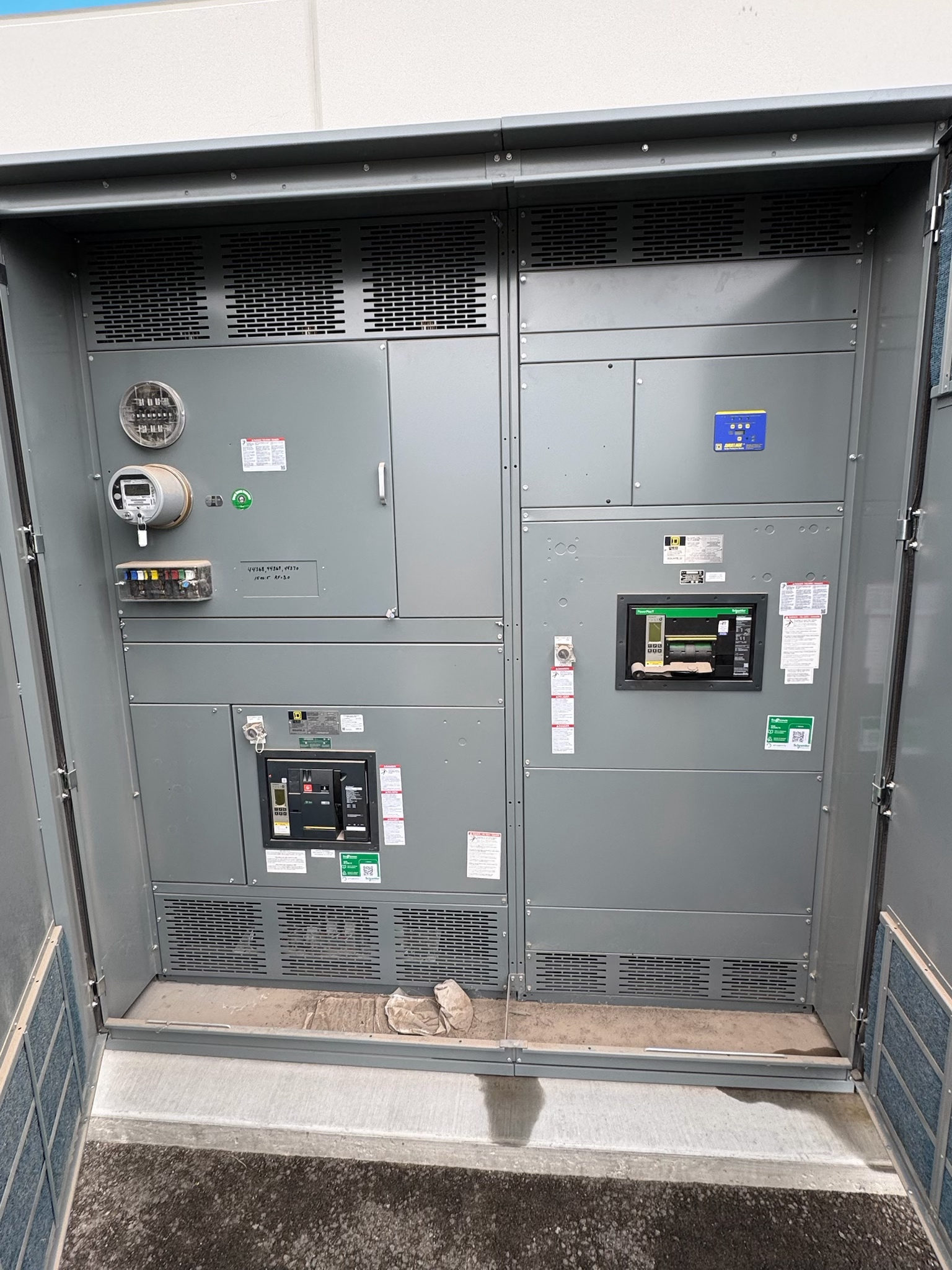
Disconnect Switch Definition and Purpose
A disconnect switch is a switching device intended to isolate a circuit or equipment from its source within the device’s assigned duty. In a switchgear lineup, it may provide a visible or otherwise specified isolating function for maintenance planning, circuit configuration, or equipment separation. Its role is not defined by its name alone: the design and operating instructions determine what switching actions it is suitable to perform.
A disconnect switch should not be treated as a universal substitute for a circuit breaker or as proof that equipment is safe to access. Whether it can make or interrupt load current, operate under particular fault conditions, or provide a specified isolation indication depends on its design and verified ratings. Qualified electrical professionals must establish the required function and safe work procedures for the installation.
Isolation Duty Is Not the Same as Fault Interruption
The central distinction in a disconnect switch definition is its intended switching duty. Some devices are intended to isolate a circuit after current has been interrupted elsewhere; other designs may have additional, explicitly rated switching duties. A disconnect switch should not be assumed capable of interrupting normal load current or clearing a short circuit unless its documented design and ratings permit that operation.
Project teams should identify which device performs normal switching and fault clearing, and how the disconnect switch relates to it. Depending on the system, that may involve a circuit breaker, fuse, interlock, or another switching device. The protection scheme and operating sequence need review as a complete arrangement; selecting an isolating component in isolation can leave gaps in functional coordination or create unsafe assumptions.
Inputs That Shape Equipment Selection
Selection begins with the electrical system and the purpose of isolation: system voltage, continuous current, available fault conditions, grounding method, frequency, and the connected load all matter. The required making, carrying, or interrupting duties must be stated rather than inferred. Designers also need to establish whether operation is manual or motorized, how often switching is expected, and whether the device belongs indoors or outdoors.
Physical and operational inputs matter as well. Confirm mounting arrangement, conductor entry and exit, bus connections, clearances, enclosure environment, access and operating direction, and how the switch will be maintained. The equipment’s interfaces with upstream and downstream devices, controls, protective relays, and interlocks should be defined. Final ratings, construction, and applicable standards depend on the complete design and project requirements.
Design Choices and System Interfaces
A new switchgear assembly can be configured around the required isolation point, but the switch must fit the lineup’s electrical and mechanical arrangement. Design decisions may include pole arrangement, operating mechanism, position indication, interlocking approach, barriers, and connection details. The team should determine what indication is required to verify device position and whether the isolation point must be coordinated with grounding provisions or other equipment.
Interfaces deserve particular attention when the disconnect switch is part of a larger assembly. Confirm how it connects to buswork and field conductors, how control power or remote signals are handled if applicable, and which devices must be in a particular state before operation. Interlock logic and operating sequences should be reviewed against the one-line diagram and written procedures. No feature or configuration should be presumed available until it is included in the project specification and confirmed for the design.
Coordination, Documentation, and Verification
Before equipment release, compare the switch’s stated duties with the protective-device coordination, fault study, one-line diagram, and operating sequence. The switch’s capabilities must align with the system conditions at its installation point; a familiar device label or a rating from a different application is not adequate verification. Review applicable standards for the specific assembly and device rather than assuming one standard or listing covers every type of switchgear.
Submittal review should resolve ratings, connection details, control and interlock diagrams, enclosure requirements, and any required position indication. Testing and inspection should follow the applicable design, project documents, and governing requirements. UL 891 may apply to suitable switchboard assemblies, but it does not automatically apply to every disconnect switch or switchgear product. Qualified electrical professionals and relevant authorities should confirm the project’s compliance path.
Specify New Switchgear with Clear Next Steps
For a new-equipment request, provide the one-line diagram, system voltage and current requirements, available fault information, equipment location, conductor and bus interfaces, and the intended isolation sequence. Include the upstream protective device, downstream load, required operating method, control or interlock needs, and any environmental or access constraints. Identify which requirements are mandatory and which may be resolved during engineering review.
A manufacturer can use those inputs to determine whether a disconnect switch is appropriate for the intended duty and how it should integrate into a custom assembly. For projects in Austin or elsewhere in Central Texas, early coordination on site interfaces, submittal timing, and delivery logistics helps align equipment planning with the project schedule; shipping can also be arranged nationwide. Lead time depends on the project and confirmed design. Before procurement, have the responsible electrical professionals resolve open ratings, applicable standards, and acceptance requirements.
Project specification checklist
Use this checklist to organize the details for a project-specific review. Final ratings, applicable standards and equipment selections depend on the approved design.
| Item | What to confirm |
|---|---|
| Isolation purpose | Confirm the circuit or equipment to be isolated and the intended operating sequence. |
| System conditions | Provide project voltage, current, grounding, frequency, and available fault information for design review. |
| Switching duty | State whether isolation only is required or whether any additional switching duty must be verified. |
| Protection coordination | Identify associated breakers, fuses, relays, and interlocks, and confirm their coordinated functions. |
| Assembly interfaces | Specify bus and conductor connections, mounting, enclosure environment, controls, indication, and access needs. |
| Compliance and verification | Confirm applicable standards, required submittals, inspection, and testing with qualified professionals and relevant authorities. |