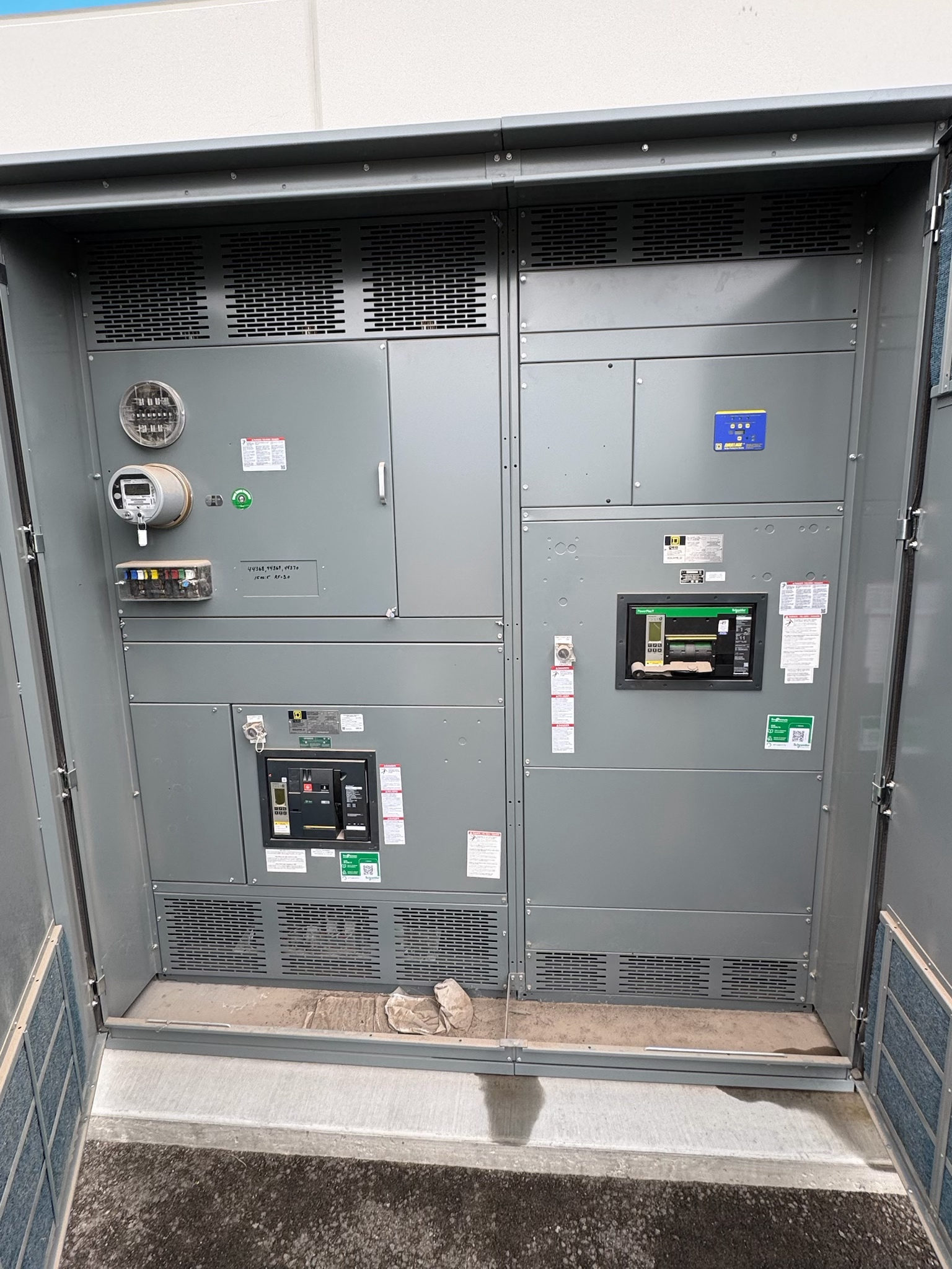
Where Utility-Facing Switchgear Fits
Utility switchgear applications arise wherever an electrical project must connect, distribute, protect or control power at a utility interface. Examples may include substations, generation or storage facilities, water and wastewater infrastructure, and large customer sites with utility-defined service arrangements. The equipment’s role can range from switching and isolation to protection and distribution, but the exact boundary between utility and customer responsibilities varies by project. For owners and project teams in Central Texas, identifying that boundary early helps prevent a design from assigning a function to the wrong assembly or assuming that utility practices are uniform.
Start with the one-line diagram and identify the incoming source, ownership demarcation, downstream loads, and any alternate feeds or operating configurations. Confirm who specifies, supplies, reviews, operates and maintains each part of the interface. These answers guide whether a project needs a switchboard, medium-voltage switchgear or another equipment arrangement; the terms are not interchangeable. A new equipment package should be selected for its defined electrical role, rather than from a broad application label alone.
Establish the Utility Interface Before Design
Utility coordination is a design input, not a final paperwork step. Obtain the applicable service requirements and review process from the serving utility, then reconcile them with the owner’s project criteria and the engineer’s design. Confirm the point of connection, metering provisions, required switching or isolation functions, protection responsibilities, control and communications expectations, and access or operating constraints. Requirements can differ by utility, service arrangement and facility, so do not assume that a detail accepted on another project applies in Central Texas or elsewhere.
Record open questions in a responsibility matrix and track their resolution through design reviews. Where the utility has not yet confirmed a requirement, mark the assumption clearly and identify its effect on layout, procurement and schedule. Coordinate equipment drawings and interfaces with the utility’s review milestones before release for manufacture. This process helps expose conflicts while changes are still manageable and gives the manufacturer a defined basis for preparing a custom assembly to project specifications.
Select Equipment Around Verified Duty
Selection depends on documented electrical conditions and the functions the equipment must perform. The engineer should establish system voltage, continuous load, available fault current, grounding arrangement, switching duties, protection scheme and operating sequence for the specific installation. Enclosure and environmental requirements also need project review, including indoor or outdoor placement, site conditions, clearances and access. No single amperage, voltage, short-circuit rating or enclosure type is suitable by default; each must be verified against the application, system study, applicable standards and authority requirements.
The equipment category matters as well. A low-voltage switchboard and medium-voltage switchgear serve different design contexts and follow different applicable requirements. UL 891 may apply to suitable switchboard assemblies, but it is not a blanket designation for every utility-facing product or voltage class. Ask the design team to identify the required equipment type, ratings, features and governing standards in the project specification. This gives suppliers a consistent technical basis for evaluating scope without substituting assumptions for engineering decisions.
Define Protection, Controls and Physical Layout
Utility-facing assemblies can involve more than power conductors and switching devices. Protection relays, instrument transformers, metering provisions, control power, communications interfaces and interlocks may be part of the defined scope, depending on the approved design. The project team should specify which functions belong in the new equipment, which are furnished separately, and what signals or terminals must be available at the interface. Confirm relay settings and coordination responsibilities with the protection engineer and utility as applicable; equipment scope alone does not establish an approved protection scheme.
Physical integration deserves equal attention. Check room or pad arrangements, cable entry and termination requirements, equipment access, working clearances and the route to adjacent systems against the project documents and applicable rules. Review interface drawings for mismatched connection points or omitted control wiring before fabrication. For a custom assembly, a clear equipment boundary and coordinated drawings help translate the one-line diagram into a buildable package while leaving final site layout and installation decisions with the project’s qualified professionals.
Coordinate Reviews, Testing and Procurement
Plan review and verification around the project’s actual requirements. Identify which drawings, data and submittals the engineer, owner and serving utility need, who will review them, and when comments must be resolved. The specification should state any required factory checks, functional demonstrations, witness points or documentation, rather than relying on a general expectation that all projects follow the same test program. Applicable testing and standards depend on the equipment design and project; confirm the required scope with the responsible engineer and relevant authorities.
When requesting pricing and schedule information for new switchgear, provide a complete design basis: one-line diagram, equipment schedules, interface requirements, preliminary layout, applicable standards and a list of open decisions. A US manufacturer building with all-American components can develop custom assemblies to specification and ship nationwide. Lead time is determined by project, design maturity, review cycles and defined scope, so request a project-specific estimate after the technical package is understood. This helps compare proposals on scope and assumptions, not just headline schedule.
A Practical Path from Concept to Release
For a Central Texas project, assemble the latest one-line diagram, load and fault-study information, utility service documents, site constraints and owner requirements before seeking a firm equipment proposal. Ask the engineer to flag unresolved ratings, protection functions, metering details and utility review items. Then request a scope review that identifies included equipment, interfaces, exclusions, required submittals and the information still needed to finalize the design. This sequence is useful whether the project is a new facility, an expansion or a replacement, because it ties procurement to verified conditions rather than a generic application description.
Before authorizing manufacture, confirm that the selected assembly matches the approved design, utility comments have been addressed where required, and the project team understands its testing and documentation obligations. Qualified electrical professionals should review the specification and drawings, and relevant authorities should resolve applicable approvals. Keep a controlled record of the final one-line, equipment data, settings responsibilities and interface documents for later project coordination. These concrete checks make the next step clear: close design questions, align stakeholders, then procure equipment against a defined and reviewable scope.
Project specification checklist
Use this checklist to organize the details for a project-specific review. Final ratings, applicable standards and equipment selections depend on the approved design.
| Item | What to confirm |
|---|---|
| Utility demarcation | Confirm ownership, operating responsibility and the electrical point of connection. |
| System duty | Verify voltage, load, fault conditions, grounding and switching duties for this project. |
| Equipment category | Identify the required switchboard or switchgear type and applicable standards. |
| Protection and interfaces | Define relay, metering, control, communications and connection responsibilities. |
| Reviews and verification | Document utility review milestones, required submittals and project-specific testing. |
| Procurement basis | Provide current drawings, specifications, site constraints and open design decisions. |