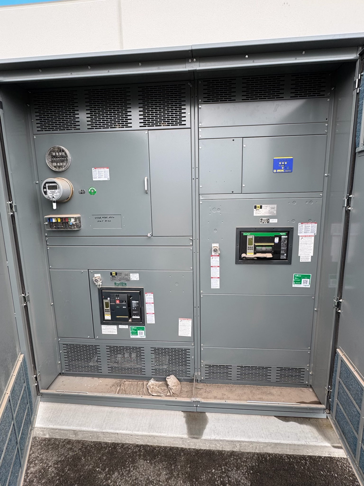
Start with the motor duty and driven load
MCC starter and protection selection begins with how each motor operates—not simply its horsepower. Identify the driven equipment, expected starts per hour, acceleration time, load inertia, operating schedule, and whether the motor starts loaded or unloaded. These characteristics affect starter type, thermal demands, and the protection approach. Record motor nameplate data, including voltage, full-load current, frequency, service factor where applicable, and connection details. Confirm whether the application involves a standard induction motor, reversing duty, jogging, or another operating mode that changes starting or stopping requirements.
Pump, fan, conveyor, compressor, and process loads can impose different starting profiles and consequences of interruption. Document any need for reduced-voltage starting, speed control, frequent cycling, or controlled acceleration, then verify that the proposed method suits both motor and load. A motor control center should reflect the actual duty cycle and operating sequence. Qualified electrical professionals should review the motor data and application before equipment is specified; assumptions based only on nominal horsepower can lead to unsuitable starters or protection settings.
Choose starter architecture for the operating sequence
The project team should compare across-the-line starters, reduced-voltage methods, and variable-frequency drives only where the process requirements support those choices. Starting current, acceleration time, torque needs, supply-system limitations, and the effect on connected equipment all matter. For reversing or jogging applications, confirm the required sequence and expected frequency of operation. Where speed must vary, define the control range and operating modes rather than treating a drive as a drop-in substitute for a starter. Selection also depends on the motor design and any manufacturer restrictions.
Specify how each unit will be controlled: local or remote commands, permissives, interlocks, status indication, and fault reporting. Identify the control power source and interfaces to the plant control system, including required signals and communication expectations. These decisions affect unit arrangement, wiring, and documentation. For new switchgear, custom MCC assemblies can be developed to project specifications, but the configuration and applicable product standards must be confirmed for the particular design. Do not presume that a specific starter type, enclosure, or listing is suitable before reviewing the application.
Coordinate overload and short-circuit protection
Motor overload protection and short-circuit protection serve different purposes and must be considered together with the starter and feeder. Determine the motor's nameplate data, starting profile, conductor information, available fault current at the equipment, and the protective devices upstream. The design professional can use those inputs to evaluate device selection and settings against the motor's operating needs and the installation requirements. A setting that avoids nuisance trips during acceleration still needs to provide appropriate protection; it should not be selected by trial or by copying values from an unrelated motor.
Protective coordination is a project objective, not a guarantee from the MCC label alone. Review the intended response to motor faults, feeder faults, and upstream events, including whether selective operation is required and what system constraints apply. Device combinations and coordination results depend on specific components, settings, fault-current conditions, and the applicable design criteria. Confirm these details with the responsible electrical engineer and relevant authorities. Ratings and standards are not universal across MCC configurations, so verify the proposed assembly and protective scheme for the actual project.
Resolve electrical and mechanical interfaces
A complete submittal basis should identify the supply characteristics, system grounding, available fault current, feeder arrangement, and intended MCC location within the distribution system. Confirm the number and types of motor units, spare-space expectations, future expansion needs, and physical constraints such as access, cable entry, and the installation environment. Voltage, current, short-circuit rating, and enclosure requirements must be selected for the project; none should be inferred from a general product description. The designer should also establish the applicable standards and any required assembly evaluation for the selected configuration.
Interfaces extend beyond power conductors. Provide control schematics, interlock logic, terminal requirements, network or monitoring interfaces, and a clear definition of which party supplies connected equipment and signals. Confirm how the MCC will connect to upstream and downstream systems and how drawings, settings, and equipment identifiers will be coordinated. Documenting these boundaries early reduces unresolved questions during design review and procurement. The customer’s qualified electrical professionals should verify that the specified equipment aligns with the installation conditions and the requirements of the authorities having jurisdiction.
Review coordination evidence and verification needs
Before release, review the proposed one-line diagram, motor schedule, unit lineup, control diagrams, and protective-device information as a coordinated package. Check that each motor's duty and starting method agree across the equipment schedule, control narrative, and protection basis. Where studies are required, confirm their assumptions, system configuration, device data, and intended operating modes. Request clarification when the documented fault-current or coordination basis does not match the proposed equipment. Any UL 891 reference should be limited to an assembly for which that standard is applicable; it does not automatically apply to every MCC or other switchgear type.
Define what verification and documentation the project requires, such as design review, factory checks, or specified test records, and confirm their scope with the manufacturer before ordering. Factory verification does not replace field installation checks or commissioning by qualified personnel. Do not plan work on energized equipment as a substitute for proper review or testing. Test procedures, acceptance criteria, and responsibilities should be agreed in advance and aligned with the final design. Applicable standards and required evaluations depend on the selected assembly and project; confirm them rather than assuming a listing or test scope.
Build a procurement-ready motor schedule
For a useful quotation and design review, submit the motor schedule, nameplate data, load descriptions, starting and operating sequences, system voltage, available fault-current information, and protection or coordination requirements. Include control-system interface details, drawings, environmental and enclosure requirements, lineup constraints, and the applicable project standards. Mark unresolved inputs explicitly so they can be addressed before the design is finalized. This helps distinguish firm requirements from preferences and gives the manufacturer a basis to develop a new MCC assembly to specification. Lead time is project-dependent, so request a schedule review against the required delivery window rather than assuming availability.
A practical next step is to hold a design-basis review with the project engineer and equipment supplier. Resolve starter selections, device coordination responsibilities, ratings, interfaces, documentation, and verification scope before purchase release. Confirm any requested UL 891 assembly treatment only where relevant to the specific design. The manufacturer builds in the USA using all-American components and can ship nationwide; those facts do not replace project-specific engineering review. This focused review helps align the motor application with the equipment package and surfaces missing information while design choices can still be addressed.
Project specification checklist
Use this checklist to organize the details for a project-specific review. Final ratings, applicable standards and equipment selections depend on the approved design.
| Item | What to confirm |
|---|---|
| Motor and load data | Confirm nameplate information, load type, duty cycle, starts per hour, acceleration needs, and operating modes. |
| Starting method | Document starting torque and current needs, supply limitations, and whether reduced-voltage starting or speed control is required. |
| Protection and coordination | Provide available fault current, upstream device data, coordination objectives, and the responsible study or setting basis. |
| MCC electrical and physical requirements | Verify system characteristics, required ratings, lineup arrangement, enclosure conditions, cable access, and applicable standards. |
| Control interfaces | Define commands, permissives, interlocks, control power, status points, network interfaces, and wiring boundaries. |
| Verification and procurement | Agree on submittals, review responsibilities, requested factory checks or records, and project-dependent delivery timing. |