Start With the Submittal Set and Its Revision Status
A submittal drawing review checklist helps project teams confirm that proposed new switchgear reflects the approved design before fabrication. Begin by identifying every document in the package: general arrangement, one-line diagram, wiring diagrams, bills of material, control schematics, and applicable product data. Record each drawing number, revision, issue date, and review status. Confirm that the package identifies the project and equipment lineup consistently, including section names and designations used on plans and schedules.
Compare the submittal against the latest contract documents and approved clarifications, not an earlier bid set. Check whether comments from prior reviews have been incorporated and whether unresolved exceptions are clearly listed. A marked-up drawing may communicate a change, but it does not by itself establish that the change is accepted. Route technical questions to the responsible electrical engineer and document decisions so purchasing, construction, and commissioning teams work from the same approved revision.
Verify Ratings Against the Application
Review the equipment ratings shown on the one-line and nameplate data against project requirements. Depending on the equipment and application, these may include system voltage, frequency, continuous current, short-circuit withstand or interrupting ratings, and the ratings of buses and devices. Confirm that the specified values align with the available system information and the design basis. Do not treat a rating shown on one component as proof that the complete assembly meets the required rating.
Check protective-device types, trip or fuse selections, and coordination notes against the approved protection study or design documents where applicable. Confirm the intended source, load, and tie arrangements, including whether the drawing represents normal operation, alternate sources, or future provisions. Ratings and applicable standards depend on assembly design and project conditions; qualified electrical professionals must resolve inconsistencies before approval. Identify any assumptions requiring confirmation rather than silently accepting them as established facts.
Check Dimensions, Access, and Site Interfaces
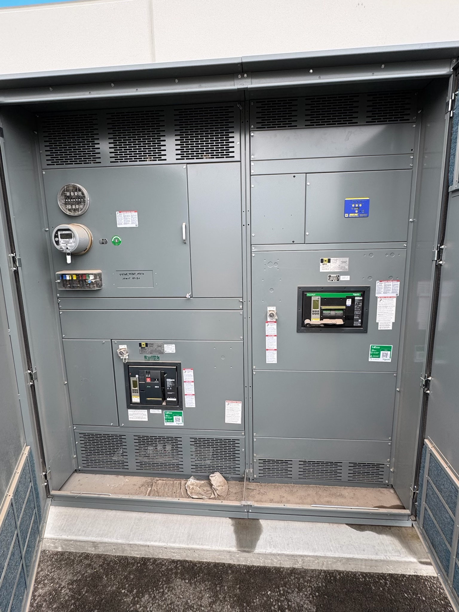
Compare overall lineup width, height, depth, section breaks, and equipment weights, when provided, with architectural and electrical plans. Verify working-space and access requirements using the project documents and applicable rules; do not infer adequate clearance from a front elevation alone. Check door swing, removable covers, cable access, ventilation needs, and the route from receiving area to final location. Confirm whether floor openings, housekeeping pads, sleeves, or other construction interfaces are shown and coordinated.
Review incoming and outgoing cable entry locations, termination space, conduit zones, and bus connections against the installation design. Confirm that cable sizes and quantities used for the layout match current schedules and that connection details are compatible with the intended conductors and lugs, as specified. If drawings show a different entry direction or section arrangement than the plans, raise the issue before release. Site dimensions and routing constraints should be verified by the project team; the submittal alone cannot establish field fit.
Trace Controls, Metering, and Documents
For controls, metering, and documents, trace each required function across the one-line, control schematics, terminal plans, and interface schedules. Confirm which devices are included, what signals are exchanged, and where responsibility passes to another system or contractor. Review control power source, operating modes, interlocks, alarms, and remote indications against the sequence of operation. Check metering quantities and measurement points, then verify that specified communications or hardwired outputs match the monitoring system requirements.
Document interface details precisely: signal type, terminal identification, polarity where relevant, protocol and communication parameters when specified, and who provides field wiring or network configuration. Avoid assuming that a drawing symbol establishes compatibility with a building management, supervisory, or utility system. Request clarification for missing points, mismatched tags, or undocumented dependencies. Confirm that the document index includes the revisions needed for construction and that marked changes are carried consistently into related diagrams and schedules.
Coordinate Comments, Exceptions, and Verification
Organize review comments by drawing number and revision, with a clear location, issue, and requested resolution. Separate required corrections from questions and informational notes. Check cross-document consistency after changes: a revised breaker designation, for example, may affect the one-line, wiring diagram, device schedule, and control sequence. Ask the manufacturer to identify drawing impacts when a project decision changes an interface, rating, or physical arrangement, and ensure the revised documents replace superseded copies in the review record.
Before approval, agree on what will be verified during any applicable factory testing or document review, including control functions and metering interfaces that are within the approved scope. Test procedures and acceptance criteria should follow the project requirements and applicable standards, as determined for the equipment. Factory checks do not replace field installation inspections or commissioning. Qualified personnel should plan and perform testing under appropriate safety procedures; this checklist is for document coordination, not instructions for working on energized equipment.
Close the Review Before Releasing Procurement
Turn the review into a controlled release package. List open items, responsible parties, due dates, and the drawing revisions that must be returned; identify decisions that affect long-lead components or fabrication sequencing without assuming a particular lead time. Confirm the approved configuration, required accessories, labeling conventions, and shipping or receiving constraints from project documents. For custom assemblies, provide complete, coordinated inputs and identify which requirements are mandatory versus preferences so the design can be reviewed against a stable basis.
Before release, verify that the final approved set includes resolved comments, current schedules, and consistent equipment identifiers, and distribute it to the engineer, contractor, controls team, and other responsible reviewers as appropriate. For new switchgear, submit project-specific electrical, physical, and interface requirements early enough to clarify conflicts before fabrication. The manufacturer can review the requested design and applicable standards for the proposed assembly; ratings, dimensions, listings, and compliance remain subject to design review and project verification by qualified professionals and relevant authorities.
Project specification checklist
Use this checklist to organize the details for a project-specific review. Final ratings, applicable standards and equipment selections depend on the approved design.
| Item | What to confirm |
|---|---|
| Revision control | Confirm drawing numbers, issue dates, revision clouds, comment disposition, and the current approved set. |
| Electrical ratings | Compare system and assembly ratings with the design basis, available system data, and approved protection requirements. |
| Physical fit | Verify lineup dimensions, access, cable entry, termination space, and construction interfaces against coordinated plans. |
| Controls and metering | Match devices, points, signals, terminals, communications, and responsibilities to control narratives and system schedules. |
| Testing and release | Confirm applicable review or factory test scope, acceptance criteria, resolved comments, and release-document distribution. |