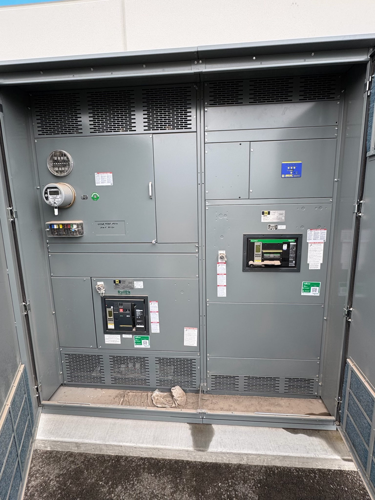
Purpose of the Equipment Ground Bus
An equipment ground bus provides a common conductive path for bonding the metal parts and grounding connections identified in a switchgear design. Its role is distinct from the normal current-carrying phase bus and from a neutral bus, even when these conductors are located in the same assembly. For a facility purchasing new switchgear, the bus is one part of a larger grounding and electrical interface: its connection points must align with the incoming and outgoing equipment, the grounding conductors, and the project’s grounding scheme.
The appropriate arrangement depends on the equipment type, system design, and installation conditions. A ground bus should not be selected by assuming a particular size, fault duty, or configuration will suit every installation. The project team should define what equipment is to be bonded, where external grounding conductors enter or leave, and how continuity is maintained across sections and adjoining gear. Those decisions give the manufacturer a concrete basis for configuring the assembly.
Define Connections and Interfaces Early
Document the intended interfaces before finalizing the switchgear design. Relevant inputs include the one-line diagram, grounding and bonding requirements, equipment lineup arrangement, conductor entry direction, and details of adjacent equipment or enclosures. Identify whether grounding connections are required at incoming and outgoing compartments, at lineup ends, or at specific field connection points. Connection location and access matter: a point that is electrically suitable may still conflict with cable routing, barriers, or installation clearances.
The project should also clarify who provides conductors, lugs, bonding jumpers, and connections between separate equipment sections. Do not assume a building grounding electrode conductor, grounding electrode system, or external ground grid is included with the switchgear. These are project interfaces that need clear ownership and coordination. Provide the required connection method and conductor information in the specifications, subject to design review; avoid relying on a generic note such as “ground bus as required” when the installation depends on defined termination locations.
Select for the Actual Electrical Design
Selection involves more than naming an equipment ground bus. The responsible electrical professional must establish the applicable grounding scheme and determine the ground-fault and bonding duties the assembly must address. Confirm the switchgear type, system voltage, available fault conditions, protective-device coordination, and other design criteria needed to evaluate the assembly. These factors can affect bus design and connections, but no single bus size or short-circuit rating is appropriate for every project.
Specify the required bus material or construction only when the project documents call for it, and coordinate that choice with the manufacturer’s proposed assembly. Confirm how joints, section transitions, and connections to doors or removable parts are handled where bonding is required. Enclosure construction, environmental conditions, and installation details may also affect the grounding interface. Applicable standards and any listing requirements depend on the particular design and equipment; UL 891 applies to suitable switchboards and should not be presumed to apply to every switchgear assembly.
Maintain Continuity Across the Lineup
A continuous grounding path depends on the complete assembly, not just the presence of a bus in one section. Review how bus sections connect to one another, how lineup extensions are treated, and how adjoining equipment interfaces are bonded. Where the design includes separately shipped sections or field-assembled joints, the drawings and instructions should identify the required connection points and assembly details. The project team should verify that those details remain compatible with shipping splits, site layout, and the final lineup sequence.
Continuity also requires coordination around surfaces and components that may be painted, coated, removable, or subject to movement. The design should identify the intended bonding method rather than leave installers to infer it. Qualified personnel should inspect the completed assembly and connections using procedures appropriate to the equipment and project. Any continuity or bonding checks should follow approved documentation and applicable requirements; this discussion is not a reason to work on energized equipment. Resolve discrepancies before energization through the project’s established review process.
Coordinate Drawings, Review, and Verification
Submittal review is an opportunity to compare the proposed ground bus arrangement with the project’s grounding plan. Check the equipment outline and connection locations against conductor routes, cable entry, adjacent gear, and available working space. Review bus and bonding details, lineup joints, and any required field connections alongside the one-line diagram and grounding notes. If the project specifies a particular connection interface or requires a defined test or inspection record, identify it before approval so responsibilities and documentation are clear.
After design approval, changes to lineup arrangement, entry direction, adjacent equipment, or grounding conductor routing can affect the interface. Route revisions through the project’s engineering review rather than assuming the original arrangement still fits. Verification should be performed by qualified electrical professionals under applicable project procedures and relevant authority requirements. The manufacturer’s design information can support this review, but final suitability depends on the complete installation and confirmed project conditions.
Prepare a Clear Procurement Package
To request a new switchgear proposal, provide the one-line diagram, equipment schedule, grounding and bonding notes, lineup and room layout, and the required conductor entry and termination information. Include available system and fault data, applicable project specifications, and any interface drawings for adjacent equipment. Mark which connections are factory-configured and which are expected in the field. If UL 891 is specified, identify the assembly to which it applies and have the manufacturer confirm applicability during design review rather than treating it as a blanket requirement.
Before release, reconcile the approved drawings with the purchase specification and installation responsibilities. Confirm ground bus connection locations, section-to-section continuity provisions, field bonding work, and the documents needed for inspection or testing. For Central Texas projects, coordinate drawing approvals, shipping sequence, site access, and the receiving team’s ability to inspect and stage the equipment; nationwide shipment is available, while timing depends on project requirements. A complete interface package reduces avoidable clarification and gives qualified project professionals the information needed to evaluate the new assembly for its intended installation.
Project specification checklist
Use this checklist to organize the details for a project-specific review. Final ratings, applicable standards and equipment selections depend on the approved design.
| Item | What to confirm |
|---|---|
| Grounding scheme | Confirm the project’s grounding method and the bus’s intended role in the complete system. |
| Connection points | Identify required termination locations, conductor routing, connection methods, and access constraints. |
| Lineup continuity | Document section joints, shipping splits, extensions, and bonding interfaces that must maintain continuity. |
| Electrical design data | Provide system voltage, available fault information, and other criteria required for project-specific evaluation. |
| Standards and verification | Confirm applicable standards, any assembly-specific listing requirement, and project inspection or testing procedures. |
| Scope and procurement inputs | Clarify factory versus field connections and provide drawings, schedules, specifications, and adjacent-equipment interfaces. |