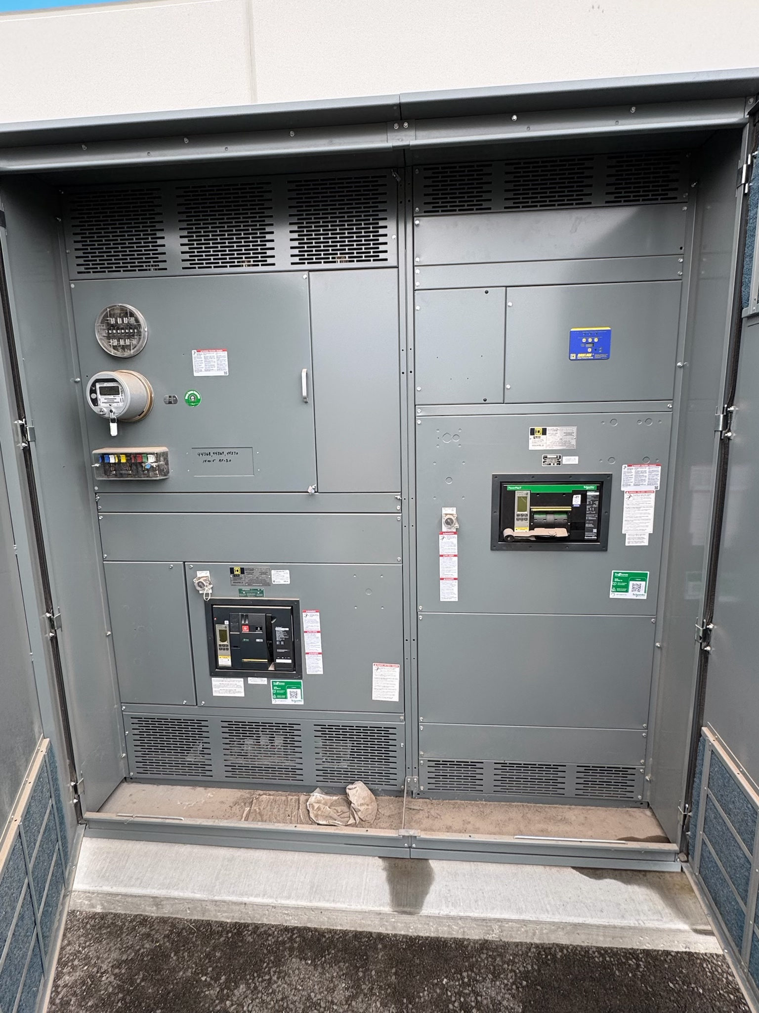
Compare the rating with available fault current
An interrupting rating describes the fault current a specific protective device is designed and tested to interrupt under stated conditions. Prospective fault current is the current the electrical system could deliver at a point if a short circuit occurred, before the protective device clears it. Selecting new switchgear requires comparing these values at the device’s actual location; a rating cannot be judged in isolation or treated as a system-wide capability.
The available fault current must not exceed the applicable interrupting rating for the device and conditions of use. This comparison is distinct from the assembly’s short-circuit or withstand ratings, which address how equipment tolerates fault current for a specified duration or until protective devices operate. The engineer must verify each relevant rating and its relationship to the complete assembly.
Establish the fault-current basis
A defensible comparison starts with project-specific system data: nominal voltage, source configuration, transformer information, conductor characteristics and lengths, and the operating arrangements that can affect fault contribution. Utility contribution data may be needed at the service point. On-site generators, motors, alternate feeds, and ties can also affect the available fault current, depending on how the system is configured and operated.
The study should identify fault current at each point where a protective device will be applied, not rely on a value from a different bus or operating condition. The responsible electrical professional determines appropriate assumptions and study methods, then documents the basis. If source details or future operating modes are unknown, flag them for resolution rather than assuming the lowest fault-current case is sufficient.
Select devices for voltage and duty
Device selection considers more than a headline interrupting rating. Confirm the device type, system voltage, applicable rating basis, and the manufacturer’s documented conditions for using that rating. The project engineer should compare the calculated prospective fault current with the rating applicable to the actual installation and verify that the selected equipment’s short-circuit and fault ratings meet the system duty.
An interrupting rating does not, by itself, establish that a switchboard or switchgear assembly is suitable for the installation. Assembly ratings, protective-device combinations, and any conditions or limitations must be checked against the project design and applicable standards. UL 891 applies to suitable switchboard assemblies where appropriate; it is not a blanket claim for all switchgear or fault-rating arrangements. Applicable standards and any listing requirements depend on equipment design and project review.
Coordinate interfaces and protection
Ratings depend on interfaces across the electrical system. The equipment designer needs clear information about incoming sources, transformers, bus connections, feeder devices, tie breakers, generators, and planned future connections. The protection engineer should assess device settings and coordination alongside fault-current adequacy. Coordination seeks appropriate selective operation where required, but it does not increase a device’s interrupting rating or make an otherwise inadequate rating acceptable.
Where a project proposes a tested or documented series combination of upstream and downstream devices, confirm that the exact devices, ratings, voltage, and installation conditions match the supporting documentation and project requirements. Do not infer a combination rating from device labels alone. Changes to sources, transformer data, conductor routing, or protective-device selections can alter the analysis, so the design team should communicate revisions before equipment is finalized.
Review evidence and testing scope
For procurement, request documentation that lets the engineering team verify the proposed device and assembly against the approved design: equipment descriptions, applicable ratings, protective-device details, and any conditions associated with the rating basis. Confirm that submittals match the one-line diagram and fault-current study, including identified sources and operating arrangements. Resolve discrepancies before release rather than treating a catalog value as project approval.
Factory testing and field commissioning have defined scopes and do not substitute for a fault-current study or proof of a rating beyond its documented basis. The project team should determine which inspections, tests, and records are required for the equipment and installation. Qualified electrical professionals and relevant authorities review the design and compliance. Any changes after the study or submittal review should trigger evaluation of whether the fault-current comparison and coordination remain valid.
Prepare a complete equipment request
When requesting new switchgear, provide the latest one-line diagram, voltage and source details, fault-current study or stated study status, operating configurations, and protective-device requirements. Identify known future sources or expansion plans and note unresolved utility or transformer data. Ask the manufacturer to propose equipment against these inputs and clearly identify ratings, assumptions, and any items requiring engineering confirmation. Custom assemblies can be developed to specification, but the project team remains responsible for approving suitability.
For Austin and Central Texas projects, coordinate data and submittal review among the owner, electrical engineer, utility or other source providers, and equipment supplier early enough to address open questions before release. A US-built assembly using all-American components and nationwide shipping may suit a project’s procurement preferences, but it does not replace technical verification. Lead time is project-dependent; confirm timing with the equipment scope and required approvals.
Project specification checklist
Use this checklist to organize the details for a project-specific review. Final ratings, applicable standards and equipment selections depend on the approved design.
| Item | What to confirm |
|---|---|
| Device location | Confirm the prospective fault current at each protective device’s point of application. |
| System data | Provide voltage, source configuration, transformer and conductor data, and relevant operating modes. |
| Device rating basis | Verify the applicable interrupting rating, device type, voltage, and conditions for use. |
| Assembly fault ratings | Confirm the equipment assembly’s short-circuit and withstand ratings separately from device interrupting ratings. |
| Protection interfaces | Review upstream and downstream devices, settings, ties, alternate sources, and any documented combinations. |
| Design evidence | Align the fault-current study, one-line diagram, equipment submittals, testing scope, and required approvals. |