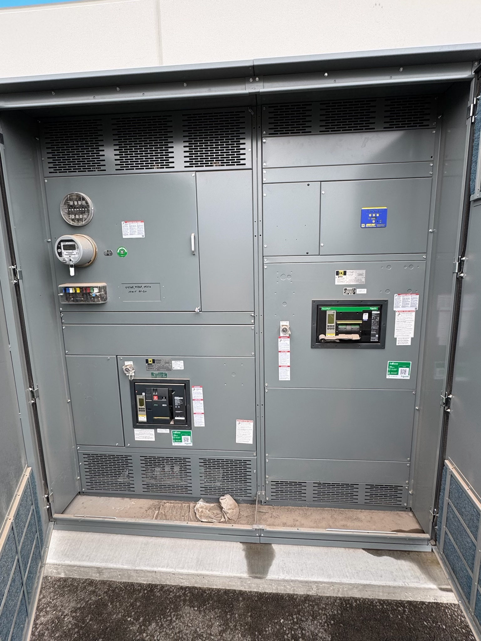
Start with the Distribution Equipment Glossary
Distribution equipment carries electrical power from a source to downstream circuits, while providing ways to control, protect, and isolate those circuits. For a new switchgear project, shared definitions help owners, engineers, contractors, and manufacturers discuss the same design decisions. Terms such as switchboard, switchgear, bus, and protective device are related, but they are not interchangeable labels for every assembly.
Use this glossary as a starting point, not as a substitute for project documents. The one-line diagram, load information, available fault current, operating requirements, and applicable codes shape what equipment is appropriate. For Central Texas projects, coordinate early among the design professional, electrical contractor, utility or source provider as applicable, and equipment supplier. Confirm each term against the actual specification before requesting a proposal.
Switchboard and Switchgear: Define the Assembly
A switchboard is an assembly of devices used to distribute and control power, commonly organized around a main section and feeder sections. Switchgear is a broader term often used for assemblies that switch, protect, and isolate electrical circuits; the exact construction and governing standards depend on the equipment type and application. In some contexts, the terms overlap in everyday conversation, so the equipment description in the project specification matters more than the label alone.
When reviewing new switchgear, identify the intended function, system voltage, configuration, environment, and required ratings rather than assuming a familiar name establishes suitability. UL 891 applies to suitable switchboards and assemblies, not automatically to every product called switchgear. Ask which standard and evaluation apply to the specific design, and verify that the proposed assembly matches the specification and authority requirements.
Bus, Main, and Feeder: Trace the Power Path
The bus is a conductive path within an assembly that connects incoming power to outgoing circuits. The main device controls or protects the incoming connection, while feeder devices serve downstream loads or panels. A one-line diagram shows these relationships in simplified form and is an essential reference for determining the number and arrangement of sections, mains, and feeders. The terms describe functions; they do not by themselves establish capacity or protective performance.
For selection, reconcile the diagram with load schedules, source details, future circuit needs, and the available fault-current information. Confirm conductor and bus requirements, device types, connection points, and any metering or control needs with the project engineer. Do not infer ampacity or short-circuit capability from appearance or a term in a glossary. Those ratings must be specified and checked for the actual assembly and system conditions.
Protective Devices and Interrupting Ratings
A circuit breaker or fuse interrupts current when its conditions exceed its intended operating limits. Protective devices may also provide switching or isolation functions, depending on their design and application. An interrupting rating describes a device’s ability to interrupt a specified fault current under defined conditions; it is distinct from the equipment’s overall short-circuit rating. These values must be coordinated with the system and cannot be treated as universal capabilities.
Selection requires review of available fault current, system voltage, protective-device characteristics, and the coordination goals established for the installation. Protection settings and device combinations can affect which circuits remain energized during a fault, but decisions belong with qualified electrical professionals. Check that the proposed equipment data and documentation address the project’s specified conditions. Have the design team resolve mismatches before release for manufacture, rather than relying on assumptions based on an earlier installation.
Enclosure, Sections, and Project-Specific Design
An enclosure houses and protects electrical components; its construction and environmental suitability depend on the installation location and applicable requirements. Sections are the connected portions that make up an assembly, and their arrangement affects access, footprint, cable entry, and future changes. A custom assembly can be developed to a project specification, but customization does not remove the need to verify clearances, interfaces, ratings, or compliance for the complete design.
Document the installation environment, available space, access and working-clearance constraints, cable routing, and connections to upstream and downstream equipment. Confirm enclosure requirements and assembly dimensions with the project team; do not assume one enclosure type fits every indoor or outdoor setting. Manufacturers build in the USA using all-American components and can develop assemblies to specification, with UL 891 assemblies where applicable. The applicable standard and listing status must be confirmed for the particular design.
From Glossary Terms to a Procurement Checklist
Before requesting new switchgear, prepare the current one-line diagram, equipment schedules, load and source information, fault-current data, and project specification. Mark unresolved items such as spare feeder provisions, metering, controls, cable entry, or physical interfaces. Ask the supplier to identify assumptions and exceptions in the proposal, and compare them against the engineer’s requirements. That process turns glossary terms into a reviewable scope and reduces avoidable clarification during design and procurement.
Plan submittal review, design coordination, and testing requirements around the project schedule; lead times depend on the project and should be confirmed rather than presumed. Determine what factory documentation or testing is specified, and coordinate acceptance and installation responsibilities with the project team. For a Central Texas site, confirm delivery access, receiving arrangements, site readiness, and coordination with the electrical contractor without assuming a local facility or fixed delivery date. Have qualified professionals and relevant authorities review the final design.
Project specification checklist
Use this checklist to organize the details for a project-specific review. Final ratings, applicable standards and equipment selections depend on the approved design.
| Item | What to confirm |
|---|---|
| System definition | Confirm nominal voltage, phase, frequency, source arrangement, and grounding from project documents. |
| Load and circuits | Verify load schedules, main and feeder functions, spare or future circuit needs, and connection details. |
| Fault and protection | Obtain available fault-current data and confirm required device and assembly ratings with the design professional. |
| Installation conditions | Document location, enclosure requirements, dimensions, access, cable entry, and equipment interfaces. |
| Standards and evaluation | Identify standards and any listing or labeling requirements applicable to the specific assembly and project. |
| Submittals and schedule | Confirm proposal assumptions, review milestones, specified testing and documentation, receiving logistics, and project-dependent lead time. |