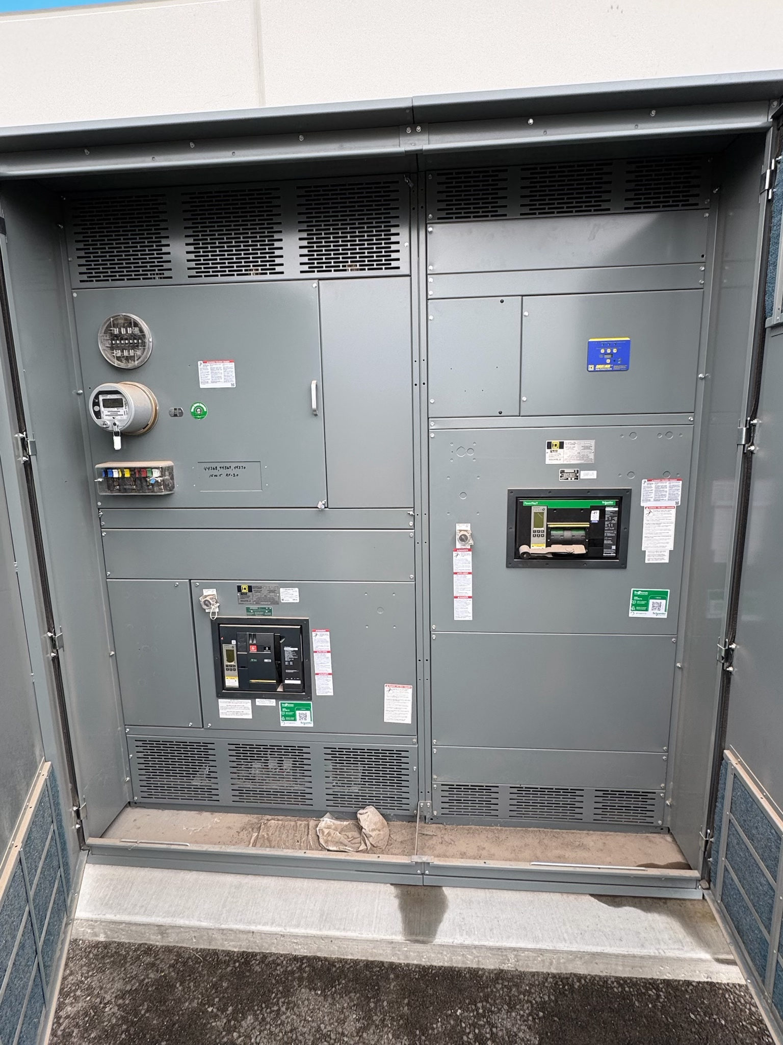
Neutral Bus Definition and Purpose
A neutral bus is a conductive bar or assembly that provides a common termination point for neutral conductors in electrical equipment. In systems where the neutral is brought into a switchboard or switchgear assembly, it connects the incoming neutral path with the neutral conductors serving applicable circuits. Its physical form, location, and connection method depend on the equipment design and project requirements.
The neutral bus is not automatically interchangeable with an equipment grounding bus. Neutral conductors carry current under normal conditions in many system arrangements; equipment grounding conductors serve a different protective function. Whether and where neutral and grounding connections are bonded is determined by the system configuration, applicable code requirements, and the designated bonding point—not by treating the two buses as one.
Where Neutral Connections Are Used
Neutral bus connections are relevant when the electrical system and connected loads require a neutral conductor. They may appear in service or distribution equipment, including new switchgear and switchboards, but the need and arrangement depend on the system being supplied. Three-phase systems, for example, do not all use the same conductor arrangement or serve the same types of loads; the project one-line diagram and equipment schedule should establish what is required.
A useful first question is whether the equipment receives a neutral, distributes neutral conductors onward, or has no neutral connection in its specified configuration. Confirm the source and load system, feeder and branch-circuit requirements, and any separately derived system interfaces. These details help prevent a design from adding an unnecessary connection or omitting a required one.
Selection Inputs for the Bus
Neutral-bus design should be based on documented project inputs rather than a generic bus size. Relevant information includes the system voltage and configuration, source and load characteristics, expected neutral loading, conductor material and termination requirements, number and size range of conductors, and the equipment arrangement. Harmonic-producing or unbalanced loads may affect neutral-current expectations, so the design team should address them where applicable instead of assuming neutral current will be negligible.
The assembly designer and qualified electrical professionals should also review available fault-current information and the equipment’s required ratings under the applicable design basis. A neutral conductor’s role in the system does not by itself establish the bus’s required capacity or short-circuit performance. Ratings, construction, and applicable standards must be verified for the particular assembly and use.
Bonding, Isolation, and Interfaces
A central design decision is whether the neutral bus is isolated from the equipment enclosure and grounding bus at that location, or bonded as required at a designated point. The correct arrangement depends on the electrical system, service or feeder context, and applicable requirements. The project drawings should clearly identify the intended bonding location and show how neutral, equipment grounding, and any bonding conductors interface with the assembly.
Coordination should include upstream equipment, downstream panels or loads, grounding and bonding details, and any transfer or separately derived system arrangements within project scope. Conflicting drawings or unclear responsibility for the bonding point can result in field questions and correction work. Resolve those interfaces during specification review with the electrical engineer, equipment supplier, installer, and authority having jurisdiction as appropriate.
Configuration Review and Verification
For a custom new switchgear assembly, provide the supplier with the one-line diagram, panel or circuit schedules, conductor and termination information, equipment layout constraints, and relevant grounding and bonding notes. Identify which neutral connections must be brought into the assembly, their intended destinations, and any space or access constraints. Review drawings for conductor entry, lug arrangement, bus placement, and separation from grounding connections before the design is released for manufacture.
Verification should follow the approved design and the requirements applicable to that equipment. The project team should define what documentation, inspections, or tests are required and who is responsible for each. UL 891 applies to suitable switchboard assemblies; it is not a blanket designation for all switchgear or every configuration. Confirm the product category, construction, and applicable standards for the specific assembly rather than assuming a listing.
Preparing a Clear Equipment Request
When requesting new equipment, state explicitly whether a neutral bus is required and attach the current electrical drawings and schedules. Include the system configuration, expected neutral connections, conductor details, bonding-point intent, and known load characteristics. Flag unresolved inputs instead of asking a manufacturer to infer them. A specification review can then identify missing information, clarify interfaces, and establish which design decisions still require direction from the responsible electrical professional.
For projects in Austin or elsewhere in Central Texas, coordinate drawing approvals, site delivery constraints, and the sequence for integrating the assembly with other equipment. A US-built manufacturer using all-American components can develop a custom assembly to specification and ship nationwide; lead time depends on the project and finalized requirements. Before procurement, confirm the approved configuration, applicable ratings and standards, required submittals, and delivery coordination with the project team.
Project specification checklist
Use this checklist to organize the details for a project-specific review. Final ratings, applicable standards and equipment selections depend on the approved design.
| Item | What to confirm |
|---|---|
| System configuration | Confirm source and load voltage, phase and conductor arrangement, and whether neutral distribution is required. |
| Neutral loading | Provide expected load characteristics, including relevant unbalanced or harmonic-producing loads for design review. |
| Conductor terminations | Specify conductor material, quantity, size range, entry direction, and termination requirements. |
| Grounding and bonding | Show the intended neutral isolation or bonding arrangement and identify the designated bonding point. |
| Assembly ratings and standards | Verify required ratings, product category, and applicable standards for the specific equipment and project. |
| Submittals and logistics | Confirm drawing review, required verification records, delivery constraints, and project-dependent lead-time coordination. |