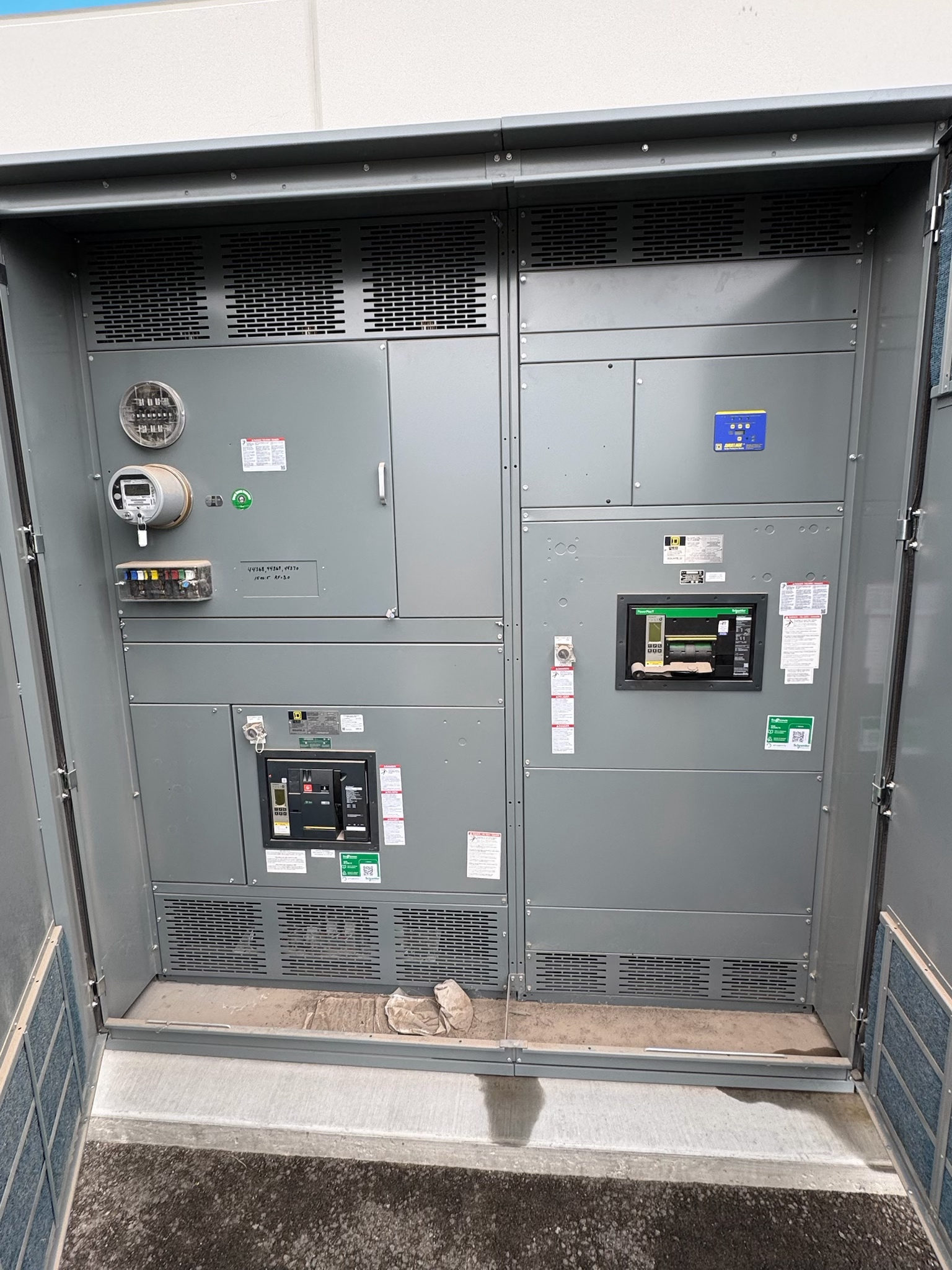
Map the Terminal’s Distribution Layers
Airport terminal distribution connects incoming utility or onsite sources to building-level switchboards, downstream panels, and specialized loads. The arrangement must match the actual project one-line diagram and operating plan; a terminal may include public areas, concessions, baggage systems, security spaces, offices, and support functions with different electrical needs. New switchgear selection starts by identifying which equipment serves each distribution layer and where isolation or metering is needed.
Document normal and alternate sources, transfer arrangements, major feeders, and the relationship between central electrical rooms and remote distribution points. Confirm whether the scope covers service equipment, distribution switchboards, or another equipment class. Applicable standards and any UL 891 suitability depend on the assembly design and project requirements; no listing or rating should be assumed before review.
Set Clear Tenant and Operator Interfaces
Terminal tenants can have distinct operating schedules, fit-outs, and responsibility boundaries. Define where landlord distribution ends and tenant equipment begins, who provides feeder protection, and how tenant loads are metered or separately managed. Include concession areas, airline spaces, retail, lounges, and other leased premises only as applicable to the project. Clear boundaries reduce ambiguity during design changes and make future tenant modifications easier to evaluate.
Coordinate electrical interfaces with the airport owner, facility operator, tenant representatives, utility, and design team. Confirm available feeder routes, connection points, access constraints, demand assumptions, and requirements for shutdown coordination. Identify who supplies final load data and who approves changes. These inputs affect switchgear configuration, protective-device coordination, metering provisions, and space allocation; they should be resolved before equipment is released for manufacture.
Size for Diverse Loads and Operating Modes
Airport loads can differ sharply in duty and operating pattern. Passenger-facing systems, baggage handling, HVAC, elevators, security equipment, and concessions may have different demand profiles, starting characteristics, or continuity requirements. Electrical professionals should use documented load schedules, demand assumptions, and operating scenarios to establish bus and feeder requirements. Review normal, peak, reduced-operation, and any planned alternate-source conditions rather than treating the terminal as one uniform load.
Confirm system voltage, phase, frequency, available fault current, grounding approach, and protective-device requirements from project documents and the serving utility. Bus ratings, interrupting or withstand capabilities, enclosure construction, and environmental conditions require project-specific verification. Consider growth allowances only with a defined basis, such as reserved feeder positions or planned capacity, and verify that the selected arrangement remains compatible with the system study and applicable standards.
Protect Essential Functions and Coordinate Controls
Determine which terminal functions require continuity, what interruption is acceptable, and how the distribution design supports the airport’s operating plan. Emergency and standby power arrangements, where included, need clearly defined source boundaries, transfer logic, interlocks, and downstream loads. Do not infer that every airport load is backed up or that a particular switchgear assembly includes transfer equipment. The engineer and owner should document the intended sequence and identify responsibility for each control interface.
Protection and controls coordination should account for upstream sources, downstream devices, and the complete system design. Confirm protective-device settings responsibility, metering and communications needs, control power, alarm points, and any required interface signals. Review coordination studies and approved drawings with qualified electrical professionals and relevant authorities. Factory inspection or testing scope should be specified in procurement documents, including the equipment and functions to be verified; energized work is not an appropriate commissioning shortcut.
Coordinate Equipment Rooms, Drawings, and Procurement
Room and route information can shape the equipment lineup as much as electrical ratings. Verify access paths, door and corridor clearances, final room dimensions, cable entry direction, working space, environmental conditions, and coordination with structural and architectural plans. Confirm whether the design calls for front-only access, a particular lineup arrangement, or future extensions; do not assume those features are available or suitable without design review. Resolve feeder termination details and interface points before approving drawings.
For procurement, provide the one-line diagram, equipment schedules, load and fault-study inputs, control schematics, specifications, and a responsibility matrix for utility, owner, tenant, and contractor interfaces. A US manufacturer using all-American components can develop custom assemblies to specification and ship nationwide; lead time depends on the project. Review submittals against the approved design, applicable standards, and installation constraints before release. UL 891 may apply to suitable switchboard assemblies, not automatically to every airport switchgear product.
Plan Expansion Around Real Terminal Changes
Future terminal work may involve new tenant spaces, added baggage equipment, electrification, or changes to operating zones. Use an approved development plan and realistic load assumptions to decide whether to reserve lineup space, feeder ways, conduit paths, or room capacity. Space reservations alone do not establish electrical capacity: bus ratings, upstream supply, fault duty, protection, and thermal conditions all need to support the eventual change. Record assumptions so later designers can distinguish planned provisions from verified capacity.
Before requesting a proposal for new switchgear, assemble current drawings, load schedules, source information, room constraints, tenant boundaries, required interfaces, and anticipated phases. Identify unresolved items and the people responsible for confirming them. Ask the design team to state equipment scope, applicable standards, testing expectations, and acceptance criteria. This focused review helps align custom equipment with airport operations while leaving final ratings, configuration, and compliance decisions to qualified professionals and the authorities governing the project.
Project specification checklist
Use this checklist to organize the details for a project-specific review. Final ratings, applicable standards and equipment selections depend on the approved design.
| Item | What to confirm |
|---|---|
| Distribution boundaries | Confirm source, building, downstream, and tenant ownership points on the one-line diagram. |
| Electrical system data | Verify voltage, phase, grounding, available fault current, and protective-device requirements. |
| Load basis | Provide load schedules, operating modes, demand assumptions, and documented growth plans. |
| Essential-load interfaces | Define alternate-source arrangements, transfer logic, controls, and continuity expectations where applicable. |
| Physical constraints | Confirm room dimensions, access route, cable entry, environment, and coordination clearances. |
| Compliance and testing | Specify applicable standards, assembly scope, submittal reviews, and factory test or inspection requirements. |