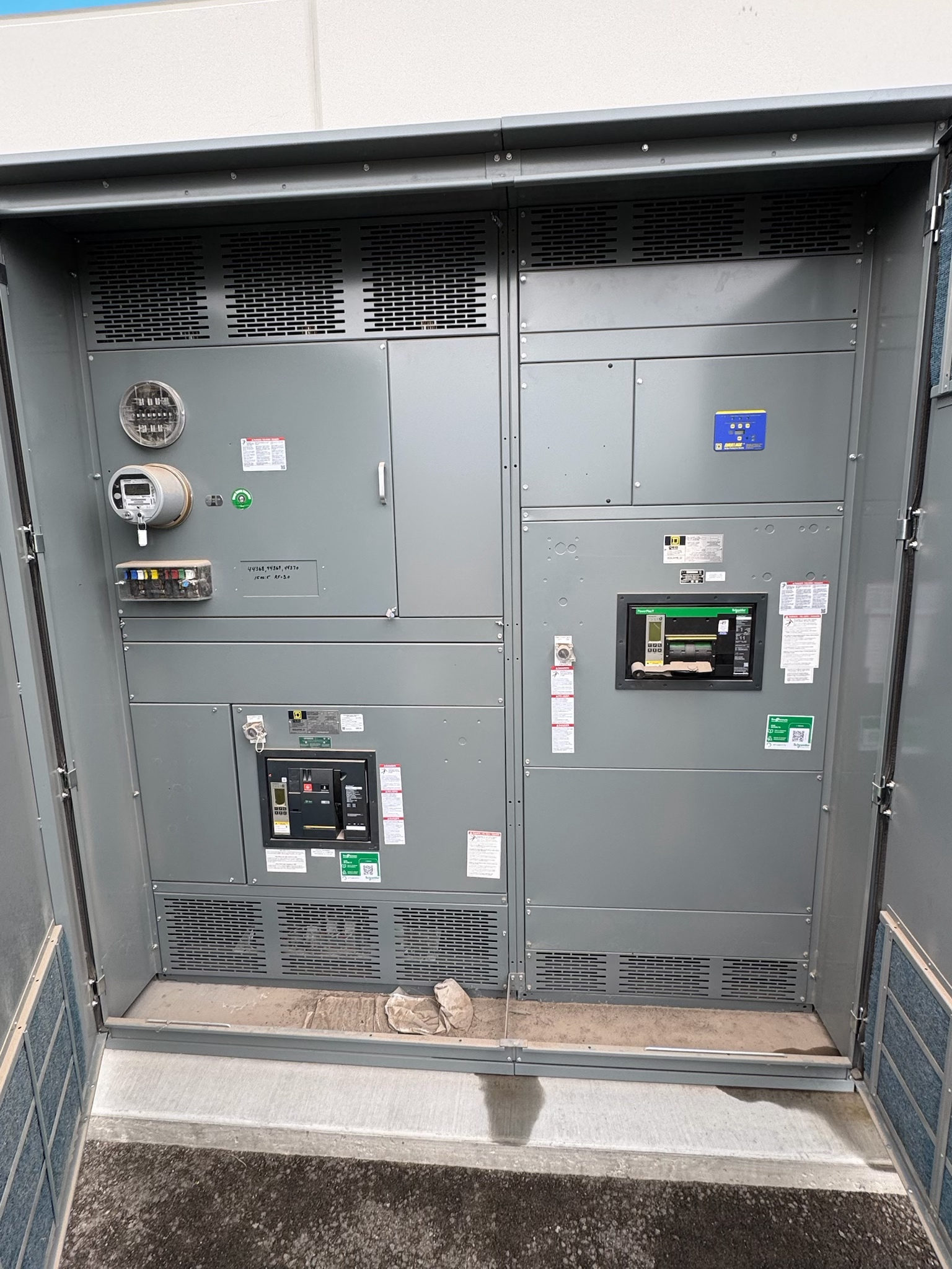
Start with the Tool Power Profile
Semiconductor tools can combine process equipment, support skids, pumps, chillers, exhaust systems, and controls, each with distinct electrical needs. A distribution design should begin with the tool manufacturer’s current electrical data and the facility’s intended tool lineup—not a general assumption about a “typical” tool. Confirm supply voltage and phase, frequency, load characteristics, connection method, grounding requirements, and any separately powered components. Identify which loads are continuous, intermittent, or subject to startup or regeneration behavior, and whether operating modes change demand.
For new semiconductor facility switchgear, these inputs help define the lineup’s function and the scope of each outgoing feeder. Include planned tool additions, spare feeder expectations, and the owner’s approach to future reconfiguration. A feeder sized only around an initial nameplate value may not address all operating conditions or connected auxiliaries. Qualified electrical professionals should reconcile tool data with the facility distribution study and applicable project requirements before equipment ratings or configurations are finalized.
Select Feeders Around Verified Loads
Tool feeders may need to serve an individual machine, a tool group, or related process-support equipment; the choice affects isolation, protection, metering, and maintenance boundaries. Confirm each feeder’s load, conductor and termination requirements, protective-device characteristics, and intended operating duty. The equipment short-circuit rating and protective-device interrupting capability must be selected from the available fault-current study and coordination requirements, not inferred from the tool’s nominal voltage or load.
Review enclosure, bus, and environmental requirements against the actual electrical-room conditions and project specification. Voltage class, current capacity, fault ratings, temperature limits, and construction details are design-specific; none should be treated as a universal switchgear capability. Consider whether feeder grouping supports clear tool identification and future changes without obscuring circuit ownership. The final selection should be reviewed by qualified electrical professionals using verified utility, transformer, distribution, and load information.
Coordinate Controls, Monitoring, and Trips
The switchgear’s control and monitoring scope should be defined with facility operations, tool engineering, and the electrical design team. Decide which conditions require local indication, remote status, alarms, metering, or control-system communication, and identify the destination and protocol requirements where applicable. Clarify whether feeder operation is manual, remotely controlled, or subject to an interlock, and document the intended control authority and operating sequence.
Protection and process controls must remain distinct but coordinated. Establish which trip conditions are required, how trip and close circuits are powered, what status points must be available, and how loss of control power is indicated or handled. Do not assume a tool interface or facility control system can accept a particular contact, signal, or communications method. Resolve interface details against equipment submittals and project standards before design release, and have qualified personnel validate protection settings and control logic.
Define the Tool and Facility Interfaces
A dependable feeder interface depends on more than the switchgear one-line diagram. Confirm the tool connection point, cable or busway approach, conductor termination details, phase identification, grounding and bonding expectations, and any required transition equipment. Coordinate physical dimensions, access clearances, cable-entry direction, routing, and equipment-room layout with the facility design and tool installation drawings. Changes to tool placement or vendor package boundaries can affect feeder locations and cable lengths, so identify who owns each connection and transition.
Semiconductor environments may also impose project-specific requirements for labeling, cleanliness, seismic design, environmental conditions, or monitoring. Treat these as items to verify rather than presumed equipment features. Document interface responsibilities among the switchgear supplier, electrical contractor, tool vendor, controls integrator, and facility team. A written interface schedule can expose missing signals, duplicated disconnects, or unassigned terminations before procurement and help prevent late changes to the switchgear lineup.
Review Coordination and Verification Needs
Before ordering, align the one-line diagram, load schedule, fault-current and coordination studies, control schematics, and tool-interface schedule. Confirm that feeder identifiers, ratings, protective functions, metering points, and remote signals agree across documents. Review the specified standards and certifications for the particular equipment type and design; applicable requirements depend on the assembly and project. UL 891 applies to suitable switchboard assemblies, not automatically to every switchgear product or voltage class.
Set expectations for submittal review and factory verification in the project documents. Depending on scope, reviews may cover construction, device selection, labeling, control wiring, and agreed functional checks. Acceptance criteria and test scope should be established by the project team; no test substitutes for site-specific installation checks or qualified commissioning. Confirm that approved settings, drawings, and test documentation will be available to the responsible professionals before energization. Work on energized equipment is not a planning or verification method.
Prepare a Procurement-Ready Package
A practical next step is to assemble the latest tool electrical schedules, facility one-line, load and fault studies, room layout, cable or busway plan, control-point list, and project specification. Mark information that is preliminary, identify the responsible party for unresolved inputs, and record expected tool phases or future feeder additions. Ask the switchgear manufacturer to review the intended configuration against these documents and identify decisions needed to develop a complete proposal and submittal package.
For an Austin or Central Texas project, coordinate delivery planning with the site’s receiving constraints, access route, unloading arrangements, storage conditions, and installation sequence; these depend on the facility and project schedule. The US manufacturer uses all-American components, builds custom assemblies to specification, and can ship nationwide. Lead time is project-dependent. Confirm the proposed scope, applicable standards, ratings, interfaces, and schedule in writing, then route technical decisions through qualified electrical professionals and relevant authorities before release.
Project specification checklist
Use this checklist to organize the details for a project-specific review. Final ratings, applicable standards and equipment selections depend on the approved design.
| Item | What to confirm |
|---|---|
| Tool electrical data | Confirm voltage, phase, frequency, load behavior, connection method, grounding, and auxiliary loads from current vendor documentation. |
| Feeder and protection basis | Verify feeder grouping, protective functions, fault-current study inputs, equipment ratings, and coordination requirements. |
| Controls and communications | Define remote status, alarms, metering, control authority, interlocks, signal types, and protocol needs. |
| Physical interfaces | Confirm terminations, cable or busway routing, entry direction, room conditions, access, and responsibility for transitions. |
| Standards and verification | Identify standards and certifications applicable to the specific assembly; agree on submittal review and test scope. |
| Procurement and logistics | Provide approved project documents and confirm custom scope, project-dependent lead time, delivery access, and receiving plan. |