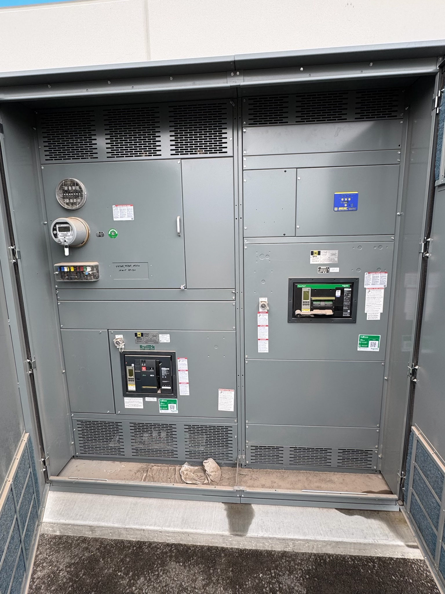
Physical Layout Starts With the Site
Physical layout engineering turns a new switchgear specification into an arrangement that can fit, arrive, and connect within the intended facility. The work begins with the available room or outdoor area, access route, equipment function, and the people and systems that must interact with it. A footprint that looks acceptable on a one-line diagram may conflict with doors, structural members, cable pathways, or adjacent equipment. Early layout review helps identify these constraints before they become costly design changes.
For a useful review, provide current architectural and electrical drawings, room dimensions, equipment schedules, single-line diagrams, and known site restrictions. Identify whether the installation is new construction or a replacement, and flag information that is preliminary. Qualified electrical professionals should verify the proposed arrangement against project requirements, applicable codes, and authority having jurisdiction expectations.
Define the Equipment Envelope
The equipment envelope includes more than the cabinet outline. Confirm the intended lineup length, depth, height, cable entry zones, access doors, removable panels, and space needed to operate or service components. These details depend on the selected equipment and project specifications; no single footprint or enclosure arrangement suits every application. Layout drawings should distinguish equipment dimensions from working and access areas so reviewers do not mistake a tight fit for a complete installation plan.
Provide the required electrical configuration and identify any future sections or expansion provisions under consideration. The design team can then assess how functional sections, bus arrangements, instrument compartments, and incoming or outgoing connections affect the physical arrangement. Changes to the electrical design can alter dimensions and interfaces, so footprint decisions should be coordinated with equipment selection rather than treated as a final architectural overlay.
Verify Clearances and Access
Clearance review must account for applicable working space, operating access, door swing, ventilation needs where relevant, and the means to remove or replace components. Required dimensions depend on equipment characteristics, voltage, installation conditions, governing requirements, and the authority reviewing the project. Do not treat a clearance shown on an early drawing as approval. Have qualified electrical and design professionals verify clearances for the specific arrangement and site conditions.
Also check the route from the building entrance to the final location: corridor widths, turns, thresholds, floor capacity, overhead obstructions, and temporary construction conditions can affect delivery and placement. Identify restricted access or sequencing needs early. A practical review compares the installed arrangement with the path used to bring each section into the space, including the room needed for handling and final positioning.
Plan Shipping Splits Before Release
Shipping splits determine how a lineup is divided for transport and later reassembled or joined at the site. They are influenced by route limits, handling equipment, access openings, section weight and dimensions, electrical arrangement, and the required field connection points. These factors need project confirmation; do not assume a standard section length or transport configuration. The intended split locations should be shown clearly and coordinated with the equipment layout and installation sequence.
Ask the project team to share delivery constraints, unloading arrangements, site access information, and any restrictions on moving large sections through the facility. Confirm who is responsible for field joining, alignment, connections, and inspection as part of the project scope. The manufacturer can review the proposed shipping arrangement against the specified equipment design, while the customer’s qualified professionals coordinate site readiness and applicable installation requirements.
Coordinate Electrical and Building Interfaces
A layout is only workable when the switchgear interfaces with the surrounding systems. Confirm incoming and outgoing conductor routes, conduit or cable entry locations, grounding provisions, control wiring, metering interfaces, and any communication connections specified for the project. Coordinate these with structural supports, floor openings, trenches, overhead pathways, and adjacent equipment. Changes to interface locations can affect both the lineup design and other disciplines’ drawings, so unresolved assumptions should be recorded and assigned for decision.
The project team should identify interface ownership: who supplies connection details, who reviews opening and support requirements, and who confirms field conditions. Compare equipment drawings with architectural, structural, and electrical documents at defined review points. Where dimensions or connection details remain pending, label them as such rather than presenting them as verified. Final coordination should reflect the approved equipment configuration and current site documentation.
Use Drawing Reviews to Resolve Decisions
Physical layout engineering is iterative. A preliminary arrangement can establish the footprint and major interfaces; subsequent reviews should resolve clearances, entry locations, shipping splits, and installation constraints. Reviewers should compare the drawings with the project specification and identify conflicts, missing dimensions, and decisions that could change the lineup. Design choices may affect accessibility, cable routing, future expansion, and coordination with other equipment, so tradeoffs should be documented rather than left to assumption.
Where factory testing is part of the project, confirm the test scope and the equipment configuration it covers. Testing can verify specified assembly functions under defined conditions, but it does not establish that the site layout, access route, field connections, or installation clearances are acceptable. Coordinate drawing approval, test expectations, and delivery planning with the responsible project parties. Applicable standards and any listing depend on the equipment design and must be confirmed for the specific assembly.
Prepare a Buildable Layout Package
Before procurement details are finalized, assemble a coordinated package with the approved equipment requirements, room or site drawings, access route, clearance criteria, interface locations, and delivery constraints. Mark the status and source of critical dimensions, identify unresolved items, and name the parties responsible for confirming them. This gives the manufacturer a clearer basis for custom assembly design and helps the project team avoid ordering against incompatible building information.
For a new switchgear project, send the latest one-line diagram, specification, dimensional constraints, and relevant architectural, structural, and cable-routing drawings for review. Ask which layout assumptions need confirmation before design release and which changes would affect footprint or shipping splits. The next practical step is a coordinated drawing review by the manufacturer and the customer’s qualified electrical professionals, followed by confirmation with relevant authorities as required. Lead time depends on the project and its finalized requirements.
Project specification checklist
Use this checklist to organize the details for a project-specific review. Final ratings, applicable standards and equipment selections depend on the approved design.
| Item | What to confirm |
|---|---|
| Site dimensions and access | Confirm room or pad dimensions, entry openings, route restrictions, overhead obstructions, and handling constraints. |
| Equipment envelope | Review lineup dimensions, section arrangement, access features, cable entry zones, and any planned future provisions. |
| Clearances | Have qualified project professionals verify required working, operating, and service spaces for the specific design and location. |
| Shipping splits | Confirm transport limits, split locations, unloading and movement plans, field joining responsibilities, and installation sequence. |
| Building and electrical interfaces | Coordinate conductor paths, grounding, control connections, supports, floor openings, and adjacent equipment. |
| Drawing and testing scope | Identify drawing approval status, open decisions, specified factory test scope, and standards or listing applicability for the assembly. |