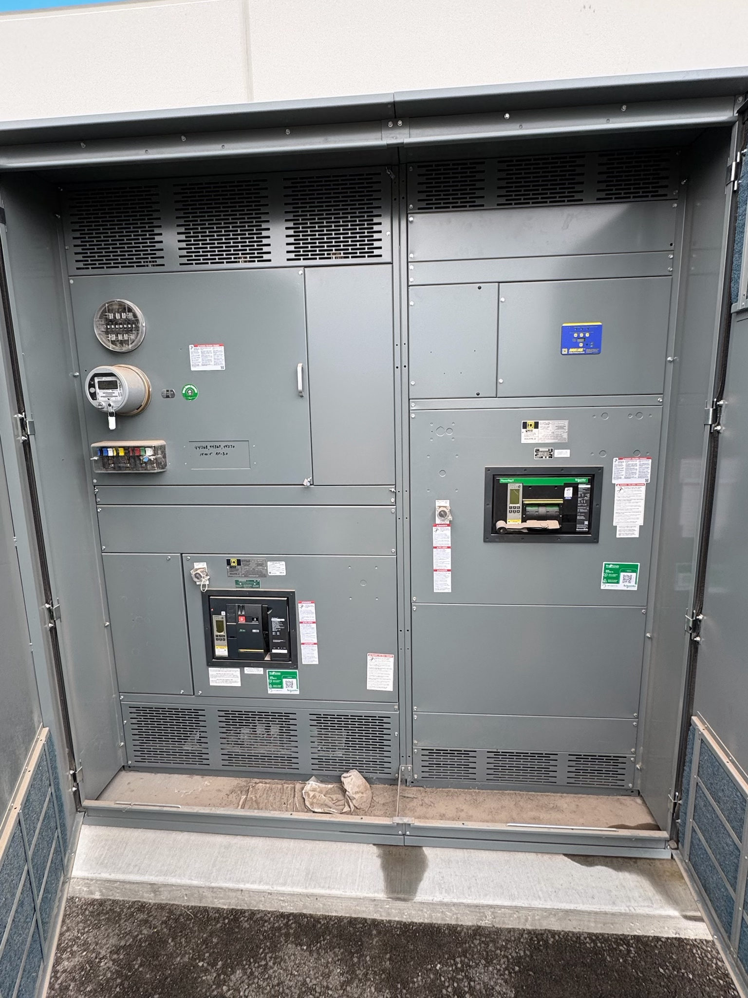
Choose the Distribution Arrangement Around the Load
Feeder and plug-in busway systems solve different distribution problems. Feeder busway carries power along a route between defined connection points, such as distribution equipment and a downstream panel or load. Plug-in busway adds approved access points along the run for compatible tap-off units, allowing loads to connect at planned locations. A project may use one arrangement or combine them, depending on the building layout, load locations, and operating needs.
For customers planning new switchgear, the key question is how power will leave the switchgear and reach the busway. Confirm whether the system needs a single end-to-end feeder, a main route with distributed takeoffs, or separate branches. That decision affects equipment interfaces, routing, protection coordination, and the information needed to define a complete assembly.
Map Loads, Routes, and Future Changes
Start with a current load schedule and a route drawing that identifies source equipment, destination equipment, tap-off locations, and major changes in direction or elevation. Record which loads are continuous, intermittent, or expected to change, and note any planned expansion without treating a forecast as a confirmed rating. The responsible electrical professional must establish design loads and verify the selected system against applicable requirements.
Plug-in busway can support access at designated points, but it does not make every location or tap-off combination suitable. Confirm the busway manufacturer’s available connection arrangements, permitted tap-off devices, spacing rules, orientation, and operating constraints for the proposed design. For feeder runs, identify the endpoints and any intermediate connections. These inputs help avoid designing around assumed flexibility that the specified system may not provide.
Define Electrical and Environmental Requirements
Provide the system voltage, phase and conductor requirements, grounding approach, source characteristics, load information, and required protection details for review. The project team must establish the necessary ampacity and fault-current withstand requirements from the actual system conditions; neither value should be inferred from a busway label or from another installation. Confirm how overcurrent protection is provided and coordinated with upstream switchgear and downstream equipment.
The installation environment also matters. Document indoor or outdoor exposure, ambient conditions, contamination concerns, space limits, access for inspection, and the route’s mounting and support conditions. Specify enclosure and ingress needs for the actual location rather than assuming a standard construction is acceptable. Applicable standards and any required listing depend on equipment design and project scope; review those requirements with qualified electrical professionals and relevant authorities.
Resolve Interfaces with Switchgear and Other Equipment
A busway order depends on more than the busway run. Identify the switchgear or other source connection, incoming and outgoing connection orientation, conductor arrangement, termination method, and physical space available at the interface. Provide equipment drawings and connection details early enough for the design teams to confirm that busway ends, switchgear bus connections, and transition pieces can be coordinated. Do not assume a direct connection will fit without review.
Coordinate the route with structural supports, ceilings, walls, fire-rated separations, other services, and access requirements. Confirm who is responsible for documenting openings, supports, transitions, and field dimensions, and when those dimensions will be verified. Where new switchgear is part of the project, align its specified configuration with the busway source interface and protection scheme. Final compatibility depends on the actual equipment and approved project drawings.
Plan Submittals, Verification, and Procurement
A useful request for quotation includes the one-line diagram, load schedule, route plan, connection points, environmental requirements, protection information, applicable project standards, and requested documentation. Include a clear division of supply between busway, tap-off units, switchgear, transitions, and related connection components. Identify project milestones and required submittal dates so design review and procurement can be coordinated; lead time is project-dependent and should be confirmed against the defined scope.
Before release, review the proposed arrangement, connection dimensions, ratings, tap-off schedule, and exceptions against the project documents. Confirm what inspection or testing documentation applies to the specified assembly and what is included in the supplier’s scope. UL 891 applies to suitable switchboard assemblies, not automatically to busway or every switchgear product. Applicable standards and verification depend on the equipment design, so request the relevant documentation rather than assuming a particular listing.
Prepare a Clear Package for Design Review
To move from concept to a reviewable package, assemble the latest one-line diagram, equipment schedules, route drawings, source and load details, and a list of unresolved decisions. Mark the proposed feeder sections and plug-in zones separately, showing intended tap-off positions and connected loads. Include interface drawings for new switchgear and note any dimensions that remain preliminary. This makes assumptions visible and gives the responsible design professionals a focused basis for checking fit, ratings, protection, and applicable requirements.
A US manufacturer of new switchgear can review custom assemblies to specification and ship nationwide, with lead times determined by the project. For an Austin or Central Texas project, share the destination and coordination milestones when requesting a quote; location alone does not establish delivery timing or site services. Ask which design inputs remain outstanding, what submittals will be provided, and which connection details require approval before release. Resolve those items with the project team before equipment is finalized.
Project specification checklist
Use this checklist to organize the details for a project-specific review. Final ratings, applicable standards and equipment selections depend on the approved design.
| Item | What to confirm |
|---|---|
| Distribution arrangement | Confirm whether the design uses feeder runs, plug-in sections, or a coordinated combination, and identify source and load endpoints. |
| Load and system data | Provide voltage, phase, conductor and grounding requirements, load schedule, and qualified design values for ampacity and fault conditions. |
| Route and tap-off plan | Show run geometry, connection points, intended plug-in locations, access needs, and required transitions. |
| Equipment interfaces | Coordinate source switchgear connections, termination details, physical dimensions, protection, and downstream equipment. |
| Environment and compliance | Document installation conditions and confirm applicable standards, enclosure needs, listing, and verification for the specific design. |
| Submittals and schedule | Define drawing and documentation requirements, scope boundaries, review milestones, and project-dependent lead-time expectations. |