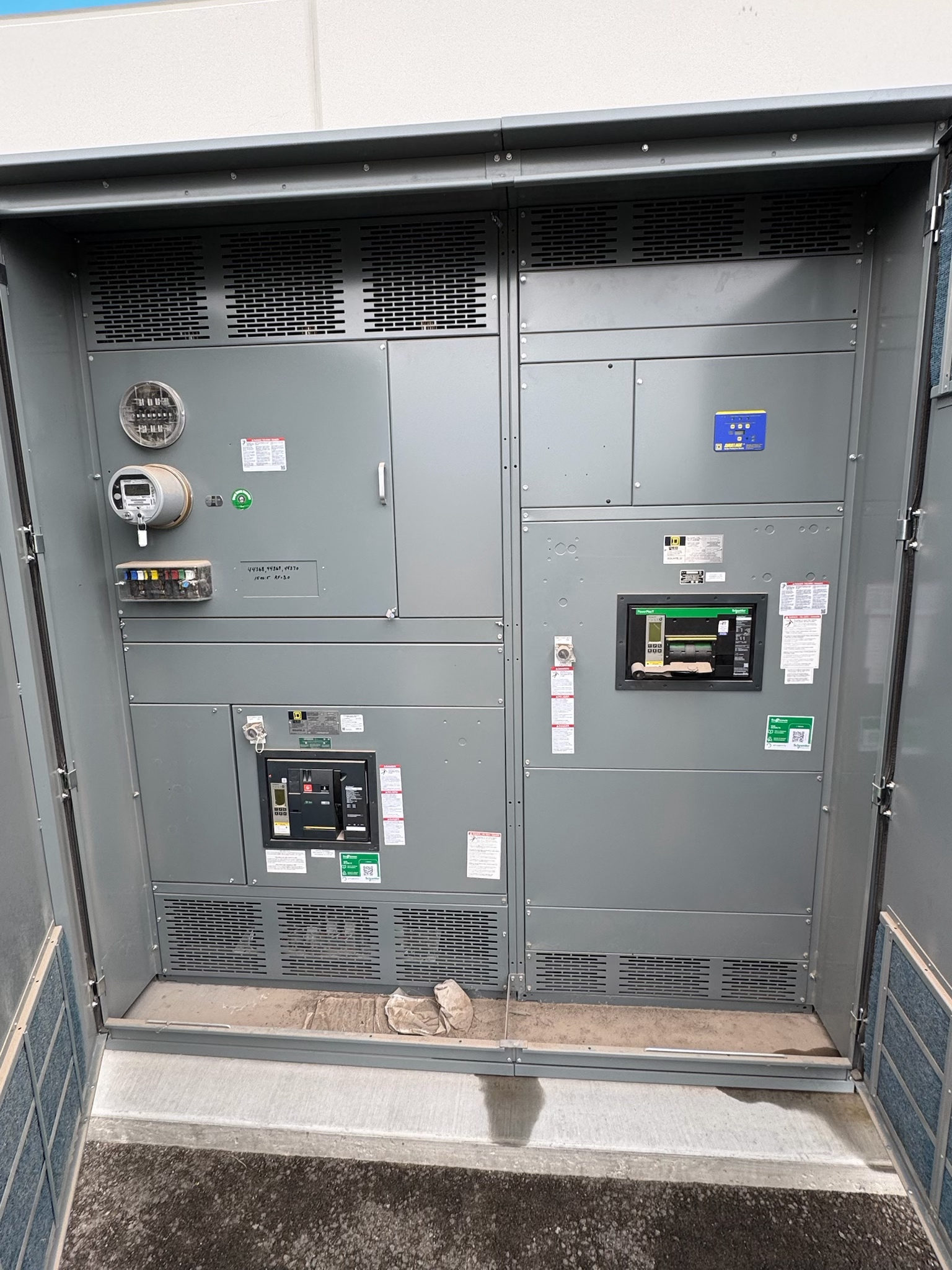
Define the High-Voltage Application
High-voltage project requirements begin with the role the equipment must perform in the electrical system. A utility interconnection, generation facility, industrial substation, or network connection can impose different operating, protection, and coordination needs. Identify the equipment boundaries: what is included in the switchgear assembly, what remains external, and where incoming and outgoing connections interface with transformers, cables, bus, grounding equipment, and control systems.
Describe normal operation as well as credible abnormal conditions. Clarify whether the equipment will connect, carry, interrupt, isolate, or ground a circuit, and whether operators need particular transfer, sectionalizing, or interlocking functions. These definitions help distinguish among equipment types and configurations; the term high-voltage switchgear alone does not establish a suitable design. A qualified electrical professional should review the one-line diagram and operating concept before equipment selection begins.
Establish System Voltage and Insulation Requirements
Provide the nominal system voltage and the highest system voltage relevant to the application, along with grounding method and expected operating conditions. Voltage selection is not just a nameplate choice: insulation coordination must account for the system, connected apparatus, switching events, and exposure to lightning or other transient overvoltages where applicable. The project team should identify required power-frequency and impulse withstand levels through the governing design basis, rather than assume values from another installation.
Environmental and installation conditions also affect insulation design. Document altitude, ambient temperature range, indoor or outdoor placement, pollution or contamination exposure, humidity, and any unusual site conditions. Confirm whether the design basis calls for air, gas, solid, or another insulation approach, and address clearances, creepage distances, and phase-to-ground coordination as applicable. The manufacturer and qualified engineers need these inputs to assess a proposed design; no insulation capability should be presumed from voltage alone.
Specify Duty and Switching Functions
Describe the electrical duty each switching device must meet, including continuous current, fault interruption, making duty, short-time withstand, and the system conditions used to establish those requirements. The available fault-current study, protection-clearing assumptions, and equipment coordination are important inputs. Values depend on the specific network and operating configuration, so they must be established and verified for the project rather than treated as universal high-voltage ratings.
State the required switching functions and operating sequence. A project may require circuit interruption, isolation, grounding, bus sectionalizing, transfer, or a defined combination, but each function must be assigned to equipment designed for it. Identify normal and alternate feeds, permitted switching states, remote or local control expectations, and mechanical or electrical interlocks. Protection schemes, instrument transformers, relays, and control power should be coordinated with the intended operation. Review these choices against the one-line diagram and operating procedures before finalizing the equipment arrangement.
Set the Applicable Standards and Design Basis
List the standards and codes specified by the owner, engineer, utility, and authority having jurisdiction, including the editions or project-specific amendments when known. Applicable requirements vary with equipment type, voltage class, installation, and jurisdiction. A standards list should be reviewed against the actual design; do not infer that a particular certification or listing applies to every high-voltage assembly. UL 891 is associated with suitable switchboard assemblies and should not be assumed to apply to high-voltage switchgear.
The design basis should also resolve required clearances, accessibility, labeling, environmental performance, seismic or other special conditions where relevant, and any owner engineering practices. Identify the responsible reviewer for each requirement and document exceptions before procurement. If the project references a standard without specifying its scope or edition, ask the engineer or authority to clarify it. This avoids using a general product description as a substitute for the technical and regulatory review needed for the installation.
Coordinate Interfaces, Testing, and Documentation
A usable specification defines interfaces as carefully as the switchgear itself. Confirm cable entry and termination arrangements, conductor and bus connections, grounding interfaces, control and protection wiring, communications, auxiliary supplies, and physical connection points to adjacent equipment. Provide drawings, available space and access constraints, and the intended division of responsibility among equipment suppliers and project contractors. These details affect compartment arrangement, connection design, and whether the proposed assembly can be integrated with the rest of the system.
Agree on design submittals, review milestones, inspection points, and acceptance or factory testing requirements before release. Test scope should follow the applicable standards, equipment design, and contract documents; do not assume a particular test or certification is included. Define required records such as drawings, test documentation, operating information, and approved deviations. Qualified professionals should review the final design and testing evidence, while site acceptance and commissioning responsibilities are established separately in the project plan.
Prepare a Complete Procurement Package
For a new switchgear quotation, assemble the one-line diagram, system study inputs, voltage and insulation basis, duty requirements, switching sequence, applicable standards, environmental conditions, interface drawings, and required documentation. Mark unresolved items explicitly and identify who will confirm them. This lets the manufacturer evaluate custom assemblies to specification without filling gaps through assumptions. US-built equipment using all-American components and nationwide shipping may be relevant procurement criteria, but they do not replace engineering review or establish a particular technical capability.
Before placing an order, compare the proposed scope against the project documents line by line. Confirm equipment boundaries, ratings and their supporting design basis, options, exclusions, submittals, testing, schedule assumptions, and customer-furnished interfaces. Lead time is project-dependent, so align the procurement schedule with design approval and required review dates rather than relying on a general estimate. Close open technical questions with the engineer, manufacturer, and relevant authorities, then retain the approved specification and drawings as the reference for subsequent coordination.
Project specification checklist
Use this checklist to organize the details for a project-specific review. Final ratings, applicable standards and equipment selections depend on the approved design.
| Item | What to confirm |
|---|---|
| System voltage and grounding | Confirm nominal and highest system voltage, grounding method, and the project basis for insulation coordination. |
| Insulation and environment | Document insulation approach, withstand requirements, altitude, temperature, contamination, humidity, and installation exposure. |
| Duty and switching function | Provide verified fault-study inputs, required operating duty, switching sequence, isolation and grounding needs, and interlocks. |
| Standards and review | Identify applicable standards, editions, owner requirements, and the engineers or authorities responsible for review. |
| Interfaces and verification | Define cable, bus, grounding, control, protection, testing, documentation, and schedule requirements for the project. |