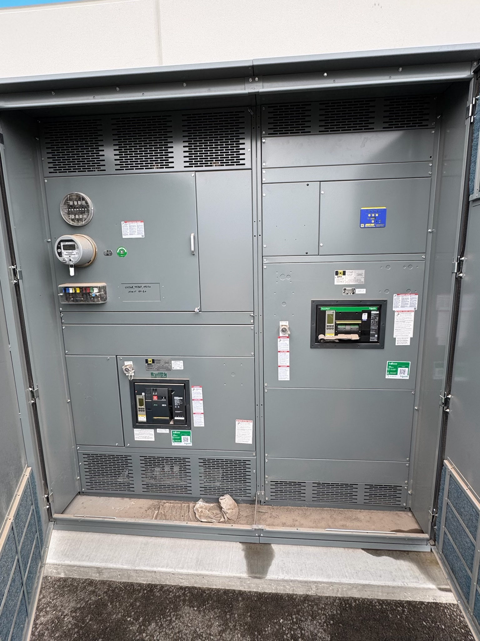
Where Low-Voltage Switchgear Fits
Low-voltage switchgear is used to control and protect electrical distribution on the low-voltage side of a power system. In a new facility or a major electrical upgrade, it may serve as a main distribution point or support defined portions of a system. The right arrangement depends on the source, connected loads, distribution plan, and the role the equipment must perform—not simply the building’s size or location.
For Central Texas projects, begin by identifying the equipment’s place in the one-line diagram and the loads it will serve. A qualified electrical professional can determine whether switchgear, a switchboard, or another assembly is appropriate for the application. This page introduces selection considerations; detailed topic pages can help address particular configurations and project requirements.
Establish the System Requirements First
Collect the current one-line diagram, service and source information, load schedules, and project specifications before comparing equipment. Confirm the system voltage, phase and frequency, expected continuous load, and whether the assembly will receive power from one source or multiple sources. Any proposed future expansion, standby source, or tie arrangement should be identified early because it can affect the lineup and its operating scheme.
The available fault current and required short-circuit performance must be established for the actual installation. These values are not interchangeable across projects, and a rating cannot be presumed suitable from a general product description. A qualified engineer should document system conditions and required ratings, then verify the proposed design against the project documents and applicable requirements.
Choose a Configuration Around Loads and Access
The distribution layout should reflect how loads are grouped, protected, and maintained. Review feeder quantities and types, breaker functions, metering needs, control requirements, and any intended source-transfer or tie operation. Decide where the main and feeder devices belong in the lineup and whether the design needs room for a defined future section. Each choice affects equipment arrangement and should be resolved against the electrical design rather than assumed from a standard layout.
Physical fit matters as much as the electrical diagram. Confirm available floor area, access and working clearances, cable entry and exit directions, conduit locations, transport path, and room conditions. Enclosure construction and environmental suitability must be selected for the installation and verified for the specific assembly. Provide drawings and site constraints early so the design can be reviewed before equipment dimensions and interfaces are finalized.
Coordinate Protection, Controls, and Interfaces
Protection and control decisions should be coordinated with the wider system. Review protective-device functions and settings with the responsible electrical engineer, including how upstream and downstream devices are intended to respond to faults. Where metering, control power, communications, or interlocking is required, define the signals, interfaces, and operating sequence in the project documents. Avoid selecting devices or settings in isolation from the system study and operating requirements.
Also identify interfaces with transformers, generators, automatic transfer equipment, bus connections, and downstream distribution. Confirm who provides each adjacent component and who is responsible for the electrical and physical connection details. A clear responsibility matrix, updated one-line diagram, and coordinated equipment schedules help resolve scope gaps before manufacturing. The final arrangement and protection approach must be reviewed by qualified professionals and the relevant authorities.
Review Standards and Verification Needs
Applicable standards depend on the equipment design and project requirements. UL 891 applies to suitable switchboard assemblies; it should not be assumed to apply to every low-voltage switchgear product or configuration. Confirm the required product type, applicable standards, and any listing expectations in the specification, and verify that they match the proposed assembly. Other equipment types and ratings may be governed by different requirements.
Before release, review drawings, device schedules, bus and connection details, control schematics, enclosure information, and nameplate requirements against the approved documents. Establish what inspections and tests are specified, who will witness or document them, and what records are needed for acceptance. Testing scope depends on the design and contract; do not assume a particular test or certification is included unless it is clearly stated and confirmed.
Plan Procurement and Project Coordination
For new switchgear, a useful procurement package includes the one-line diagram, load and feeder schedules, system study criteria, written specifications, room and cable-entry drawings, and a list of required options. Include the project schedule and decision dates, but confirm lead time for the actual design and order rather than relying on a general estimate. The manufacturer builds in the USA using all-American components, offers custom assemblies to specification, and can ship nationwide; project-specific details determine design and timing.
Coordinate design review with engineering, the electrical contractor, the equipment manufacturer, and other parties responsible for connected systems. Resolve deviations and open questions before approval, then track changes so the released drawings, field interfaces, and procurement documents stay aligned. For a Central Texas project, confirm the delivery destination, receiving access, unloading responsibilities, and site readiness with the project team; shipment logistics depend on the order and destination.
Prepare a Practical Request for Review
To begin a product review, assemble the latest one-line diagram, project specification, load and feeder schedules, available fault-current information, and room layout. Mark required voltage, phase, source arrangement, metering and control functions, feeder device needs, cable-entry preferences, and any future provisions. If a requirement is not yet established, label it as open rather than substituting an assumed rating or configuration.
Ask the manufacturer to identify the proposed assembly scope, applicable standards, design assumptions, drawing review steps, and items that remain subject to engineering confirmation. Compare the response with the project documents and route discrepancies to the responsible electrical professional before approval. This approach gives the design team a concrete basis for evaluating new low-voltage switchgear while keeping ratings, compliance, interfaces, and schedule specific to the project.
Project specification checklist
Use this checklist to organize the details for a project-specific review. Final ratings, applicable standards and equipment selections depend on the approved design.
| Item | What to confirm |
|---|---|
| System definition | Confirm voltage, phase, frequency, source arrangement, and equipment role from project documents. |
| Load and feeder plan | Provide load schedules, feeder quantities, device functions, metering, and control requirements. |
| Fault-current criteria | Document available fault current and required ratings for qualified project review. |
| Physical arrangement | Confirm room dimensions, access, cable entry, environmental conditions, and transport constraints. |
| Standards and verification | Specify applicable standards, listing expectations, inspection, testing, and required records. |
| Procurement coordination | Confirm drawing approvals, scope interfaces, project schedule, destination, receiving, and unloading responsibilities. |