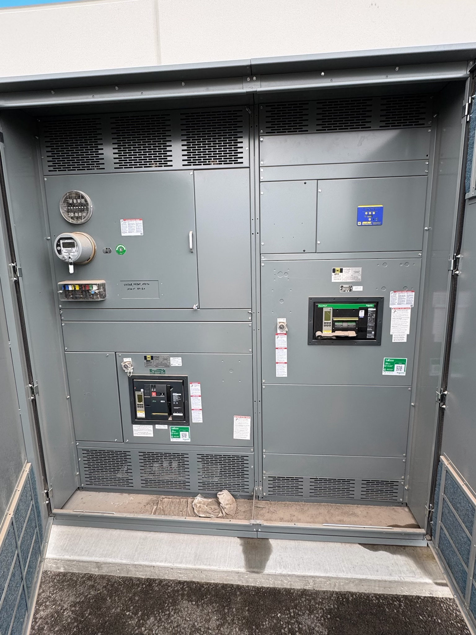
A Defined Source for Control and Metering Loads
In new switchgear, a control power transformer (CPT) supplies a lower-voltage control circuit from a source within the assembly. Depending on the design, that circuit may serve relays, contactor coils, indication, metering, or other specified devices. The transformer is a component choice, not a universal package feature: the one-line diagram, control schematic, and equipment configuration determine whether a CPT is appropriate and how it connects.
Start by identifying every intended load and its operating conditions. Controls and metering can have different voltage, continuity, and isolation needs, and a coil may impose a brief pickup demand beyond its normal holding demand. The project team should state which circuits the CPT serves, which are supplied separately, and what behavior is required if the source is lost.
Size Capacity Around Actual Operating Conditions
Select transformer capacity from the connected burden rather than from a generic switchgear rule. Gather each device’s control voltage and VA or other manufacturer-stated input data, including relay, instrument, annunciator, and coil demands. Determine which loads can operate at the same time, whether loads cycle together, and whether starting or pickup events create a momentary demand that must be considered. The design professional should evaluate the combined duty against the transformer’s applicable ratings and the project’s operating assumptions.
Also confirm the primary source voltage and frequency, required secondary voltage, expected voltage variation, and any conditions that affect the load calculation. A design with spare capacity may support planned future circuits, but that allowance should be explicit and documented rather than assumed. Final selection requires review of the actual device data and circuit design; no capacity value should be inferred without those inputs.
Coordinate Protection and Fault Behavior
Transformer protection must suit the primary source, transformer design, connected secondary circuits, and the switchgear arrangement. The project documents should identify the intended overcurrent protection and its location, along with any required secondary protection, disconnecting means, or separation between circuits. Protective-device selection and coordination are engineering decisions: available fault current, conductor characteristics, transformer inrush, device performance, and applicable requirements can all affect the result.
Clarify what the controls should do during a fault or loss of control power. A project may need defined isolation, alarm indication, or a specified response from breakers and control devices, but those behaviors belong in the control philosophy and schematics. Do not treat a CPT fuse or breaker as a substitute for the equipment’s main protective design. Applicable standards and acceptance criteria depend on the assembly and project and must be verified by qualified electrical professionals.
Resolve Wiring Interfaces Before Assembly
A useful CPT design connects cleanly to the switchgear’s primary and secondary wiring interfaces. Confirm the source connection point, secondary distribution arrangement, grounding and bonding approach, terminal identification, and the destinations of control and metering conductors. The drawings should show wire and terminal designations consistently across the one-line diagram, elementary schematics, interconnection diagrams, and terminal plans. If field conductors or external control sources are involved, define the boundary between factory wiring and project wiring.
Document the required secondary voltage and circuit references, including polarity or phase relationships where relevant to the devices and metering scheme. Establish terminal type, conductor range, and space or access expectations from the project requirements rather than assuming a standard interface. Clear interface documents help the switchgear manufacturer coordinate the CPT with relays, instruments, and the specified enclosure and layout, while giving the installing team an unambiguous connection plan.
Review Drawings, Testing, and Documentation
Before release, review the transformer’s stated input and output, capacity basis, protection, device loads, and wiring interfaces against the latest approved project documents. Check that control schematics agree with the one-line diagram and that metering requirements identify the intended sources and signals. Resolve differences in control voltage, device data, terminal numbering, or responsibility for external wiring before they become assembly or field questions. Where the assembly is designed as a UL 891 switchboard, that standard’s applicability is specific to the suitable assembly; it does not establish a listing for every CPT or switchgear configuration.
Agree on project-appropriate inspection and test documentation with the manufacturer and responsible design team. Reviews may address wiring against drawings, component identification, and specified functional checks, but the scope and acceptance criteria must be defined for the project. The document package should make the final circuit arrangement understandable for commissioning and future maintenance without implying that a particular test, listing, or approval applies automatically.
Prepare a Complete Procurement Package
For a practical quotation and design review, provide the one-line diagram, control and metering schematics, device schedule with burden data, source and secondary voltage requirements, and the intended operating sequence. Include the protection philosophy, available project fault information when established, wiring boundaries, terminal requirements, and any explicitly requested spare capacity. Identify applicable standards or owner specifications for review rather than presuming they fit every assembly. These inputs let the manufacturer evaluate a new switchgear configuration to specification and identify unresolved decisions early.
For Austin and Central Texas projects, coordinate the document review, approval milestones, shipping destination, site receiving constraints, and the party responsible for field connections. Lead time depends on the project’s design and scope; confirm it after requirements are reviewed. Before release, have qualified electrical professionals verify the load assumptions, protection, interfaces, and applicable requirements, then provide the approved drawings and a clear list of open items. This creates a concrete basis for building, shipping, and integrating the assembly.
Project specification checklist
Use this checklist to organize the details for a project-specific review. Final ratings, applicable standards and equipment selections depend on the approved design.
| Item | What to confirm |
|---|---|
| Connected loads | Confirm device list, control voltage, burden data, simultaneous operating conditions, and any pickup demand. |
| Source and secondary | Specify source voltage and frequency, required secondary voltage, and relevant operating variations. |
| Capacity basis | Document the load calculation and any explicitly required allowance for future circuits. |
| Protection and coordination | Define protective-device requirements and verify coordination against the project’s electrical design. |
| Wiring interfaces | Identify connection points, grounding approach, terminal details, circuit labels, and factory-to-field boundaries. |
| Documents and verification | Provide current diagrams and acceptance criteria; confirm applicable standards and test scope for the assembly. |