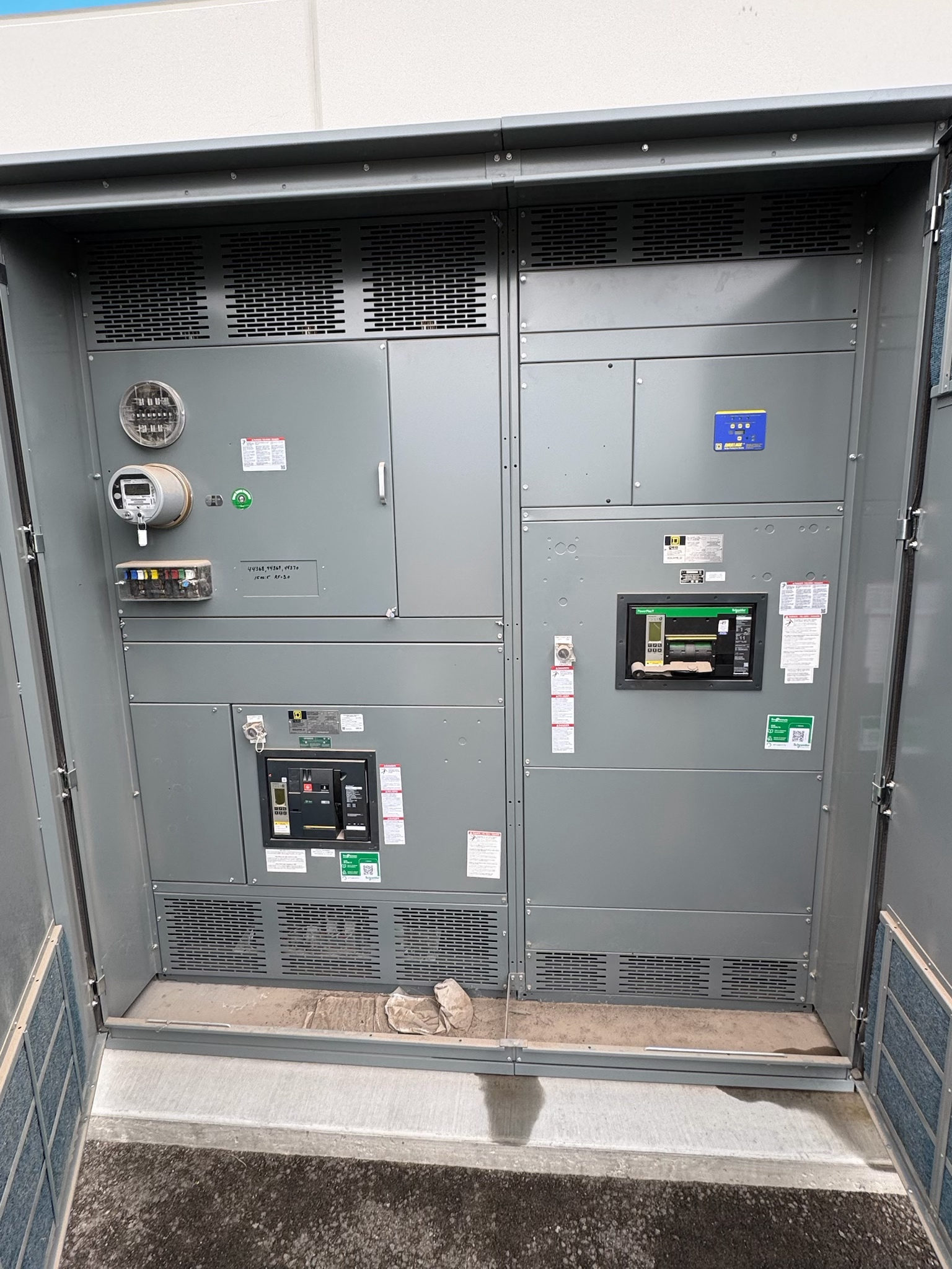
Coordination begins with the system, not a setting
Protective device coordination is the review of how protective devices respond to electrical faults and abnormal conditions across a defined system. For a new switchgear project, the objective is to establish a protection approach that addresses equipment protection, system constraints, and the desired continuity of service. Coordination is not simply selecting settings that appear to separate on a graph: it depends on verified device data, the system configuration, and the project’s operating requirements.
A qualified electrical professional should define the study scope and assess applicable codes, standards, and authority requirements for the project. The review may include upstream and downstream devices beyond the new assembly, since the equipment’s protection behavior depends on its place in the complete distribution system. Design decisions should be documented with their assumptions so they can be checked against the final equipment and installation.
Gather dependable system inputs
Useful inputs include the one-line diagram, nominal system voltage, source and transformer data, conductor information, grounding method, and the anticipated operating configurations. Available fault-current information should come from an appropriate project source and be reviewed for the relevant configurations; it should not be guessed from equipment size or a typical application. Existing protective-device models, trip-unit details, fuse types, and available manufacturer time-current data are also important when the new switchgear must coordinate with installed equipment.
Clarify which loads are critical, whether alternate sources or ties can change fault levels, and what switching states are expected. Identify motor starting, transformer energization, and other conditions that could affect device response or nuisance-trip risk. If inputs are incomplete or inconsistent, record the gap and assign responsibility for resolving it before settings or equipment selections are treated as final.
Compare device characteristics and settings
Review each candidate device’s documented operating characteristics, adjustment ranges, sensing method, and available functions against the protection objectives and the system study. Depending on the design, devices may use different trip technologies or include functions that are not present in other devices. Do not presume that a particular feature, setting range, interrupting capability, or protective function is available; confirm it for the proposed equipment and the applicable configuration.
Compare time-current characteristics across the relevant operating range, including the conditions that govern coordination and equipment protection. Check that proposed settings remain within manufacturer guidance and project constraints, and consider tolerances rather than relying on idealized curves alone. A setting that improves selectivity in one operating state may affect another state or compromise another objective. Document the selected settings, rationale, assumptions, and any unresolved overlap for qualified review.
Resolve interfaces and design choices
Protection and coordination decisions must account for interfaces between the new switchgear and the rest of the system. Confirm how the assembly connects to upstream sources, downstream feeders, transfer equipment, generators, or other relevant devices, as applicable to the project. Verify control-power arrangements, sensing connections, communications, and trip or alarm interfaces where the design uses them. The responsible design team should establish who supplies interface data and who verifies each connection and function.
Project choices may include device type, sensor or trip-unit selection, adjustable functions, trip settings, and whether a design change is needed to meet the documented objectives. These choices are constrained by the actual assembly design, available fault current, equipment ratings, and the intended operating sequence. UL 891 applies to suitable switchboard assemblies, not automatically to every switchgear product or project; applicable standards and any listing requirements must be confirmed for the specific design.
Coordinate study, review, and verification
A coordination study should use data for the actual proposed devices and clearly identify the system assumptions, configuration, settings, and coordination limits. Review curves and supporting calculations with the one-line diagram and device schedule so discrepancies are visible. Where coordination cannot be achieved across a desired range, present the limitation and practical alternatives to the project team; do not label the result selective or coordinated without defining the conditions under which that conclusion applies.
Before release and commissioning, the responsible professionals should confirm that approved device selections and settings align with the final design and equipment documentation. Project procedures may include inspection, configuration checks, or testing of relevant protective functions, performed by qualified personnel under appropriate safety controls. Testing scope and acceptance criteria should be established by the project team and applicable requirements. Work on energized equipment is not a substitute for planned, controlled verification.
Prepare procurement around approved data
For procurement of new switchgear, provide the manufacturer with the current one-line diagram, equipment schedule, study requirements, operating modes, and defined device and interface needs. Identify which settings are preliminary and which require final confirmation after system data are verified. Request review of proposed device characteristics and assembly details against the project specification, while recognizing that final engineering approval belongs to the responsible electrical professionals. Custom assemblies can be built to specification, and UL 891 assemblies are offered where applicable; applicability must be confirmed for the requested design.
Before approving submittals, reconcile device descriptions, functions, setting ranges, connection details, and coordination-study assumptions. Track revisions to source data and drawings so a change in transformer, conductor, or operating configuration triggers the right review. Confirm project-dependent lead time and nationwide shipping requirements during planning. A practical closeout is a coordinated set of approved drawings, device data, settings documentation, and verification responsibilities, with open items assigned before equipment release.
Project specification checklist
Use this checklist to organize the details for a project-specific review. Final ratings, applicable standards and equipment selections depend on the approved design.
| Item | What to confirm |
|---|---|
| System configuration | Confirm sources, ties, operating modes, grounding method, and the configurations included in the coordination review. |
| Fault-current basis | Document the source and configuration-specific available fault-current data used for device selection and study. |
| Device information | Verify proposed device models, trip technology, functions, adjustment ranges, and manufacturer time-current data. |
| Coordination objectives | Define protection priorities, desired selectivity, critical loads, and any accepted limitations across operating conditions. |
| Interfaces and verification | Identify sensing, control, trip, alarm, or communications interfaces used, plus responsible parties and project verification criteria. |
| Standards and procurement | Confirm project-specific applicable standards, listing requirements where relevant, approved submittals, and lead-time and shipping needs. |