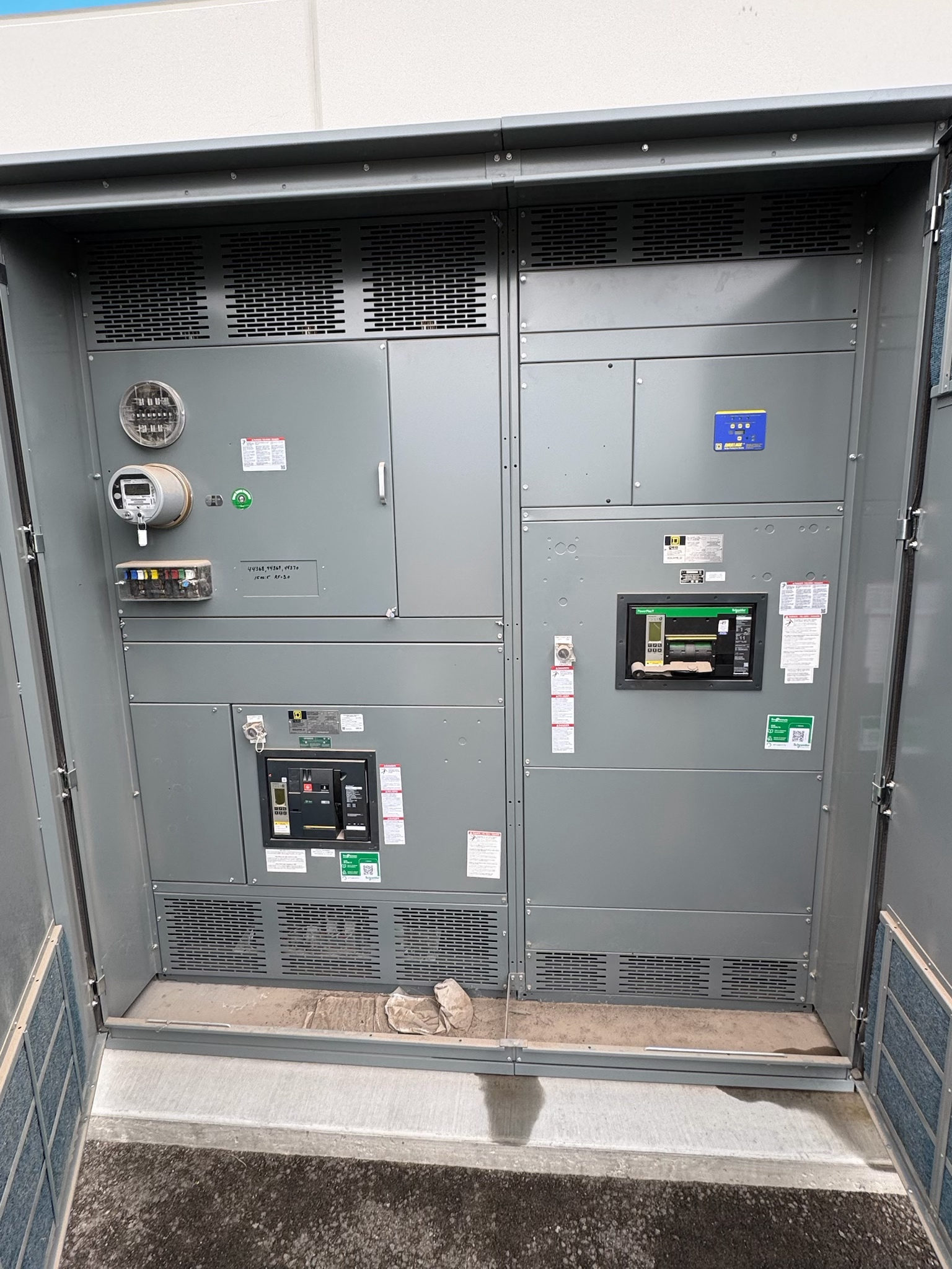
Plan coordination around essential hospital loads
Hospital selective coordination planning begins with identifying which circuits must remain energized when a protective device operates. The design team should map essential electrical system branches and other hospital loads to their sources, transfer equipment, distribution sections, and downstream devices. The applicable requirements depend on the facility, system arrangement, adopted codes, and authority having jurisdiction; do not assume one coordination rule applies to every circuit or operating condition.
For new hospital switchgear, coordination is not simply a product feature. It is a system-design objective evaluated across protective devices and source configurations. The owner’s electrical engineer, consulting engineer, and other designated project professionals should establish the required scope and document which circuits, devices, and operating modes are included before equipment is selected.
Assign study responsibility and review authority
The project should name who is responsible for the short-circuit, protective-device coordination, and related arc-flash studies, as applicable to the design scope. Responsibilities may be divided among the engineer of record, equipment manufacturer, system integrator, and other qualified parties, but the contract documents should identify who supplies models, evaluates results, selects settings, and issues final study documents. Equipment suppliers should not be presumed to own the complete facility study unless that scope is expressly assigned and supported by required inputs.
The engineer of record and owner should also define who reviews study assumptions and resolves conflicts with code requirements, operational priorities, or maintenance practices. The authority having jurisdiction determines applicable adopted requirements. Study responsibility and equipment design responsibility are related but not interchangeable: a switchgear manufacturer can build to approved project documents, while system-level conclusions require a defined engineering scope.
Gather complete system and operating inputs
Useful study inputs include one-line diagrams, nominal system voltages, utility or generator source data, available fault-current information, transformer impedances, conductor lengths and sizes, and protective-device models and settings. Include transfer switches, generator paralleling or other source arrangements, ties, and normally open points where they affect current paths. Confirm which data are preliminary and who will provide final values; assumptions that later change can affect device selection and coordination conclusions.
Hospital operating modes matter. Identify normal, emergency, maintenance, and other intended configurations, including which sources may operate together and which loads transfer between them. Capture equipment locations, available space, connection points, environmental conditions, and project-specific enclosure or access needs for the new switchgear. Qualified electrical professionals should verify the system model and assumptions against project documents and field information where applicable; a study based on incomplete or outdated data may not represent actual operation.
Define equipment interfaces and design choices
Translate the approved system design into clear switchgear requirements: source and feeder arrangement, bus configuration, protective-device types and functions, metering or controls, and interfaces with transfer equipment or downstream distribution. Confirm required voltage, continuous-current and interrupting ratings, enclosure conditions, and other ratings against the calculated system conditions and installation environment. No rating or configuration should be treated as suitable without project-specific verification.
Selective coordination can influence protective-device choices and settings, but it must be assessed across the complete relevant path and operating modes. The engineer should identify acceptable device combinations, any required time-current performance, and the limits of coordination for each source condition. Applicable product standards depend on equipment type and design. UL 891 may apply to suitable switchboard assemblies; it does not automatically apply to all hospital switchgear or establish that a complete system is coordinated.
Verify coordination and document testing scope
Coordination analysis should compare the selected protective-device characteristics under the project’s stated fault-current and operating scenarios. Review time-current curves, device settings, manufacturer data, and any coordination limitations identified by the study. Where the analysis finds a conflict or an uncoordinated region, the responsible engineer should evaluate design alternatives and document the operational tradeoffs rather than assuming a setting change is acceptable for every condition.
Define testing and commissioning interfaces in the project documents. Factory checks, routine production tests, field acceptance tests, and functional checks are distinct activities; specify which apply, who performs them, and what records are required. Testing does not replace engineering analysis, and a factory test alone does not establish system-wide selective coordination. Final settings and study documents should reflect the equipment actually furnished and approved system data, with qualified professionals directing review and any energized-work precautions.
Move from study scope to procurement
Before requesting a proposal for new switchgear, assemble the latest one-line diagram, equipment schedules, study criteria, source data status, interface requirements, and responsibility matrix. Identify open decisions—such as alternate source modes, device family constraints, physical configuration, and required submittals—so suppliers can price and engineer against a consistent basis. Confirm which items are fixed by the engineer and which may be proposed for review; do not substitute equipment or settings without the designated project approval.
A US manufacturer can build custom assemblies to specification, using all-American components, and ship nationwide; suitability, applicable standards, and lead time depend on the approved design and project requirements. For an Austin or Central Texas project, coordinate submittal milestones, site access and delivery constraints, receiving arrangements, and the timing of final study data with the project team. The practical next step is a documented scope review by qualified electrical professionals before equipment release, followed by coordinated review of drawings, study assumptions, and acceptance requirements.
Project specification checklist
Use this checklist to organize the details for a project-specific review. Final ratings, applicable standards and equipment selections depend on the approved design.
| Item | What to confirm |
|---|---|
| Coordination scope | Identify circuits, protective devices, sources, and operating modes required for evaluation. |
| Study ownership | Assign responsibility for system data, analysis, settings, review, and final study documents. |
| System inputs | Confirm one-line diagrams, source and transformer data, conductor details, device information, and data status. |
| Equipment basis | Verify project-specific voltage, current, interrupting, enclosure, and interface requirements. |
| Standards and verification | Confirm applicable product standards and required factory, field, and functional testing with the project team. |