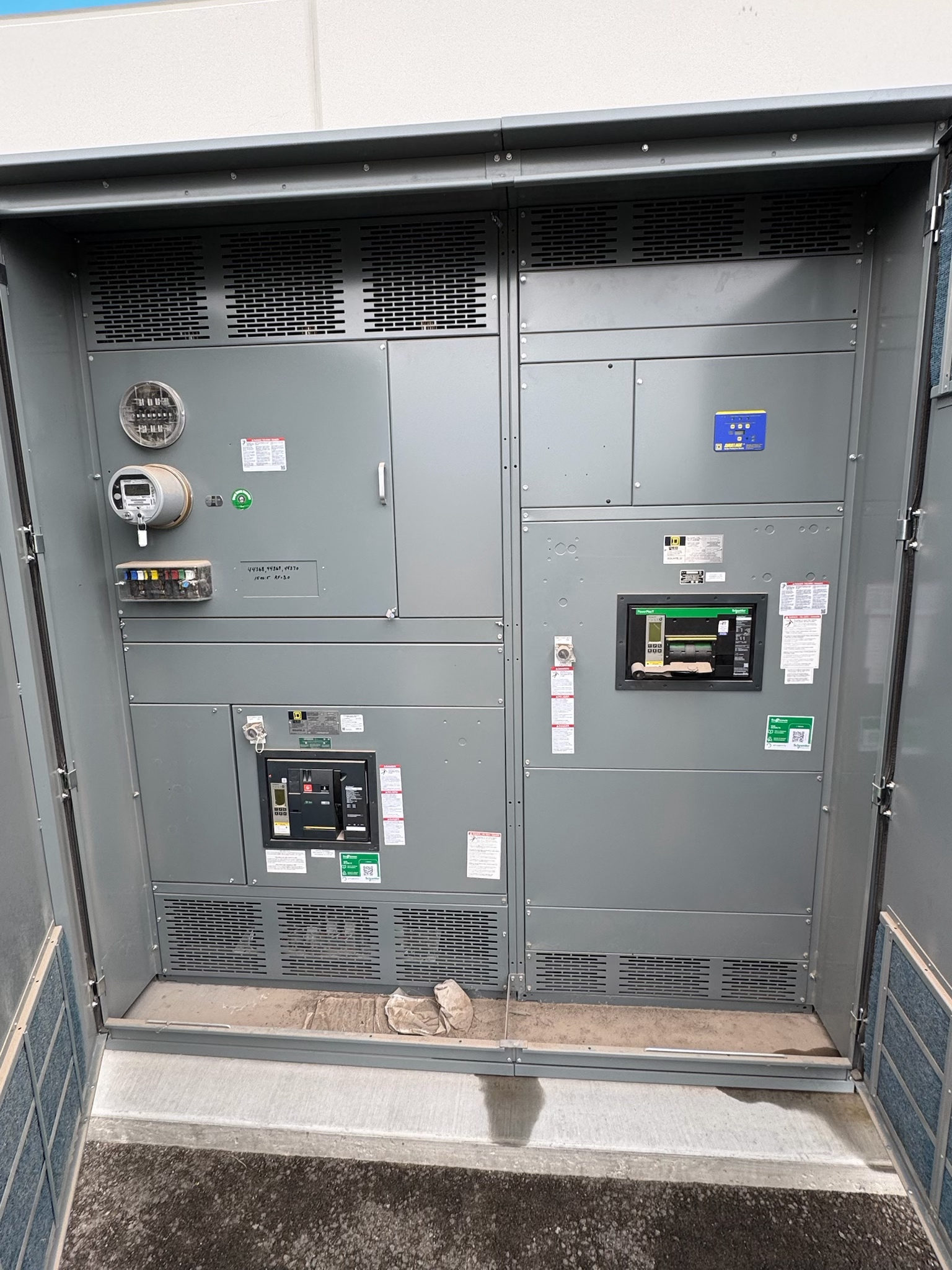
Plan for a Defined Future Need
Future expansion allowances in custom switchgear building are most useful when they address a credible next stage, not an unspecified desire for “room to grow.” A facility may anticipate added process equipment, building loads, or a later distribution branch. Each possibility affects the initial lineup differently: a reserved section, a provision for a future feeder, or capacity in upstream equipment may be relevant, and these choices are not interchangeable.
For new switchgear, begin with the expected expansion scope, approximate timing, location, and operating purpose. Identify whether the future load is known or still conceptual, and whether it will be served from the same lineup. This gives the design team a basis to evaluate physical space and electrical interfaces without treating an unconfirmed future load as an approved design condition.
Separate Spare Space From Electrical Capacity
A spare section is a physical planning allowance; it does not by itself establish that the lineup, bus, protective devices, or upstream source can support added load. Conversely, electrical capacity considerations do not ensure that a suitable section or feeder position will be available when expansion occurs. Review these issues separately, then document how they relate in the project design and operating assumptions.
The project team should confirm present and anticipated load data, demand assumptions, source configuration, and any applicable fault-duty information. Qualified electrical professionals must determine ratings and protective-device requirements for the actual system. Do not assign a future feeder a rating simply because an empty space can be reserved. The final design must be reviewed against the project specifications and applicable requirements.
Define the Future Feeder Interface
A potential future feeder interface needs more definition than a blank space on a lineup drawing. Identify the intended cable or busway approach, entry direction, termination arrangement, and the equipment or distribution point the feeder may serve. Confirm relevant conductor information when known, including material, size, quantity, and termination needs, as well as routing constraints that could affect section depth, access, or connection space.
Also establish whether the future connection is expected to be a breaker feeder, another switching arrangement, or a different interface selected by the engineer. The device, compartment, bus connection, barriers, and provisions for future work depend on the design and applicable standards. Any reserved interface should be clearly shown as a design allowance, not represented as a complete or energized feeder.
Resolve Layout and Operating Decisions
Space planning must account for the full lineup and its surroundings. Confirm available electrical-room dimensions, access and working clearances, cable-entry zones, shipping or handling constraints, and any required pathway for a later extension. The customer’s design team should identify site conditions and applicable authority requirements; dimensions and enclosure choices require project verification rather than assumptions about a standard installation.
Decide whether a future section will be installed with the initial lineup or considered for a later addition. That decision can affect the lineup arrangement, connection points, end conditions, and how the initial equipment is configured. Clarify the intended sequence of operation and whether future work could require an outage or other operational coordination. A drawing note alone cannot guarantee that later expansion will be feasible under changed site or system conditions.
Coordinate Protection, Controls, and Documentation
Future feeders can affect more than physical lineup space. Determine whether the anticipated branch may require metering, control wiring, interlocks, communications, or integration with a facility monitoring system. Identify which party will define those functions and provide interface requirements. If details are not yet available, record what is unresolved and avoid inventing control behavior or assuming that future devices will match the initial design.
Document the allowance in the one-line diagram, lineup elevation, section schedule, and relevant specifications as appropriate to the project. Distinguish equipment supplied now from reserved space or future provisions, and identify the assumptions behind each. Review coordination with upstream and downstream equipment, protection studies, and project-specific standards as the design develops. Applicable standards and any listing depend on the assembly and its intended use; they should be confirmed, not presumed.
Verify the Allowance Before Release
Before manufacturing release, have the responsible electrical professionals review the proposed expansion scenario alongside the current system design. Confirm the intended future connection point, available physical space, source and bus assumptions, fault-duty basis, protection approach, and any open engineering decisions. Where the future load is uncertain, state that uncertainty explicitly and define which items must be re-evaluated before a later feeder is specified or connected.
Testing and documentation for the initial new switchgear should reflect the approved design and scope. A reserved section does not mean a future device or interface has been installed or tested. Coordinate required submittals, inspection expectations, and acceptance criteria with the project team and relevant authorities. Record the final configuration and preserve the drawings and assumptions that a future engineer will need to reassess the expansion.
Prepare a Useful Procurement Package
For a practical quotation and design review, provide the current one-line diagram, load information, system and fault data available to the project, room and access constraints, and a clearly described expansion scenario. Include preferred lineup location, feeder destination, likely cable or busway route, anticipated controls, and the desired timing or sequence if known. Mark estimates as estimates so the manufacturer and design professionals can identify what requires confirmation.
A complete package helps distinguish a reserved section from a broader capacity or future-feeder requirement and supports project-specific decisions before fabrication. US-built new switchgear with all-American components and custom assemblies to specification may be considered where it fits the project; applicable UL 891 construction is relevant only to suitable switchboard assemblies. Lead time depends on the defined design and project. Next, resolve open inputs with the engineer, review the proposed drawings, and approve a documented scope before release.
Project specification checklist
Use this checklist to organize the details for a project-specific review. Final ratings, applicable standards and equipment selections depend on the approved design.
| Item | What to confirm |
|---|---|
| Expansion scenario | Confirm anticipated load, purpose, location, timing, and whether it will connect to this lineup. |
| Physical allowance | Define reserved section needs, lineup arrangement, access, room constraints, and future extension assumptions. |
| Feeder interface | Confirm intended connection type, route, entry direction, termination requirements, and destination. |
| Electrical basis | Provide available load, source, fault-duty, protection, and coordination information for professional review. |
| Controls and documentation | Identify metering, interlocks, communications, drawing notes, and what is included now versus reserved. |