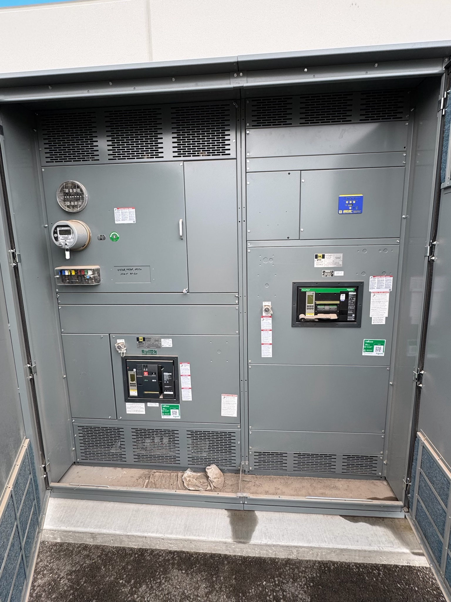
Start with the Marble Falls Water or Wastewater Process
A new controls package for a Marble Falls water or wastewater project should begin with the process it must support—not a presumed standard lineup. Identify whether the equipment serves raw-water intake, treatment, storage, distribution, lift stations, or wastewater treatment, and map each pump and motor to its operating role. Document normal, peak, and expected future operating conditions, including which pumps run together and which provide standby capacity. This information helps distinguish motor control needs from distribution and feeder functions, and clarifies whether a project calls for a switchboard, switchgear, motor-control equipment, or a coordinated combination.
Share the process sequence, one-line diagram, load schedule, and control narrative as available. For a new switchgear inquiry, identify the equipment boundaries and interfaces with drives, soft starters, motor starters, PLCs, instrumentation, and upstream or downstream distribution. These details support a design review without assuming the manufacturer is supplying every control component. Qualified electrical and process professionals should verify that the proposed arrangement fits the facility's operating requirements and applicable codes.
Match Equipment to Pump Motors and Starting Methods
Pump motors shape both the electrical design and the way operators manage flow. Provide motor nameplate information, starting method, duty cycle, expected starts, and any drive or bypass requirements. Confirm whether motors are across-the-line, soft-started, or controlled by variable-frequency drives; each arrangement affects switching, protection, coordination, and the equipment interfaces that must be accommodated. Also identify motor loads that must remain available during maintenance or changing process demand. Do not select ampacity, interrupting capacity, or short-circuit ratings from motor horsepower alone; the complete system and project conditions must be evaluated.
For multiple pumps, document lead-lag sequencing, alternation, simultaneous operation, and any interlocks that prevent unwanted starts. State which devices and signals are furnished by others, where field wiring terminates, and what status or alarm points operators need. A clear division of responsibility reduces interface gaps between new switchgear, motor-control equipment, drives, and controls. Final equipment ratings and protection settings require review by qualified electrical professionals using verified load and system data.
Account for the Installation Environment
Water and wastewater equipment may be installed in locations where moisture, condensation, temperature variation, dust, corrosive exposure, or washdown practices influence enclosure and component choices. Describe the actual installation area rather than relying on a broad label such as pump station or treatment plant. Confirm whether equipment is indoors or outdoors, the available space and access path, ventilation conditions, exposure to process chemicals, and any site-specific environmental requirements. Enclosure construction and environmental suitability must be selected for the actual location and verified against the project specification.
Include room dimensions, equipment orientation, cable-entry preferences, working clearances, and transportation constraints in the inquiry. If the equipment is near pumps or other sources of vibration, note that condition for design review. Provide existing drawings or photographs only when they accurately represent the installation area, and identify planned changes that could affect access or heat dissipation. No enclosure type or environmental rating should be assumed suitable without confirmation by the project team and relevant authorities.
Plan Standby Power and Essential Loads
Where standby power is part of a Marble Falls project, define the intended sequence before selecting equipment. Identify the generator or other standby source, transfer arrangement, loads served, and whether pumps are started sequentially to manage available capacity. Clarify which loads are essential, how controls behave during transfer, and whether a brief interruption is acceptable for each process. The switchgear and associated transfer equipment must be coordinated with the source characteristics and the project's protection and control scheme; compatibility cannot be assumed from a generator nameplate alone.
Provide available source data, transfer-switch requirements, load-priority logic, and any requirements for manual or automatic operation. Explain whether standby power serves the full facility, selected pump groups, or critical auxiliaries, and identify the intended response when a pump or source is unavailable. These choices affect feeder arrangement, interlocking, controls, and testing scope. Qualified professionals should verify system coordination, grounding, fault conditions, and applicable standards for the complete installation.
Coordinate Design Review, Interfaces, and Testing
Before fabrication, align the equipment specification with the one-line diagram, motor schedule, control narrative, and the responsibilities of other suppliers. Review lineup dimensions, access, cable entry, utility or generator interfaces, protective devices, control-power sources, and communication or alarm points. Record open questions rather than treating missing data as approval. Applicable standards depend on equipment design and project requirements; UL 891 applies to suitable switchboard assemblies and should not be presumed to cover every switchgear or controls package.
Agree on what documentation and verification are required, such as drawing review, inspection, and functional checks of specified control sequences. Define how interfaces with drives, transfer equipment, and external controls will be represented and tested, and who provides test procedures and field connections. Factory checks do not replace site acceptance, commissioning, or approval by relevant authorities. A written responsibility matrix and a current issue-for-review drawing set give the project team a practical basis for resolving mismatches before equipment is released.
Prepare a Complete New-Equipment Inquiry
To request new water and wastewater controls for a Marble Falls project, assemble the one-line diagram, load and motor schedules, process sequence, site conditions, standby-power information, and project specification. Include requested delivery timing, required submittals, shipping destination, and any phased construction constraints. Identify which items are firm and which remain under development. This lets the manufacturer review the application, identify missing design inputs, and discuss a custom assembly to specification without inventing ratings or promising a schedule before the scope is understood.
The manufacturer builds in the USA with all-American components and can ship nationwide; lead time depends on the project and should be confirmed during review. Send the package through the manufacturer's established inquiry channel and ask for clarification of scope, applicable standards, required approvals, and the information needed to finalize a proposal. Before release, have the responsible electrical professionals and authorities review the design, ratings, interfaces, and installation requirements. That sequence makes the next step concrete: a documented scope review tied to the actual pump process and site.
Project specification checklist
Use this checklist to organize the details for a project-specific review. Final ratings, applicable standards and equipment selections depend on the approved design.
| Item | What to confirm |
|---|---|
| Pump and motor schedule | Confirm motor data, starting methods, operating sequence, duty, and which pumps may run simultaneously. |
| System electrical data | Provide verified source information, one-line diagram, load schedule, and project-required ratings for engineering review. |
| Site environment and layout | Document installation location, environmental exposures, available space, access, ventilation, and cable-entry needs. |
| Standby-power scope | Define source and transfer arrangement, essential loads, pump sequencing, and control behavior during source changes. |
| Controls and interfaces | Identify drives, starters, PLC or instrumentation interfaces, signal points, and responsibility boundaries. |
| Submittals, testing, and timing | Confirm required drawings, review milestones, verification scope, shipping destination, and project-dependent lead time. |